


Manual 2100-532B
Page 25 of 46
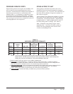
1 Maximum ESP (inches WC) shown is with 2" MERV 6 pleated filter.
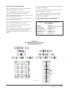
2 Rated CFM for ducted applications – required for maximum performance rating. To obtain full CFM on
models QW3S1, QW4S1 and QW5S1, locate pink wire that is secured to purple wire at low voltage terminal
strip in the control box, and attach it to the “Y2” terminal along with the purple wire.
3 Optional 2nd Stage CFM – the unit is shipped from the factory set to operate at the optional CFM level shown.
This provides lower operating sound levels for non-ducted, free discharge applications. This reduces
system capacity performance by approximately 2% at the same energy efficiency.
4 Continuous CFM the total airflow being circulated during continuous blower operation.
NOTE: These units are equipped with a variable speed (ECM) indoor motor that automatically
adjusts itself to maintain approximately the same rate of indoor airflow in both heating and
cooling, dry and wet coil conditions, and at both 230/208 or 460 volts.
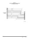
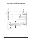
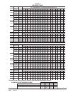
TABLE 4
INDOOR BLOWER PERFORMANCE
LEDOM
DETAR
PSE
1
PSE.XAM
4
SUOUNITNOC
WOLFRIA
EGATSts1
3
LANOITPO
EGATSdn2
EGATSdn2
1S2WQ0.05.00080080090001
1S3WQ0.05.000800905010511
1S4WQ0.05.0009051152210531
1S6WQ0.05.0009052100310541
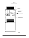
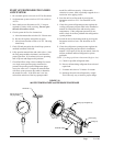
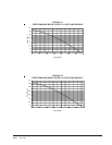
PRESSURE SERVICE PORTS
High and low pressure service ports are installed on all
units so that the system operating pressures can be
observed. Pressure charts are located on the backside of
the units lower service door, as well as later in this
Manual (Table 5). It is imperative to match the correct
pressure chart to the unit by model number. All upper
service doors must be attached to obtain proper reading.
The service ports are in the lower compressor section on
the tubing adjacent to the compressor.
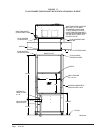
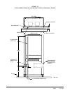
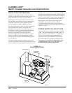
PIPING ACCESS TO UNIT
Water piping to and from the coaxial water coil is
intended to enter/exit the unit through the rectangular
hole (See Figures 1, 8A, 17 and 18). The connections on
the water coil are a double O-ring with a retainer nut
that secures it in place.
Various double O-ring fittings are available so you may
then connect to the coaxial coil with various methods
and materials. The methods include 1" barbed fittings
(straight and 90°), 1" MPT (straight and 90°), and 1¼"
hot fusion fitting with P/T fitting). (See Table 6.)
Note: All double O-ring fittings require “hand
tightening only”. Do not use a wrench or pliers as
retainer nut can be damaged with excessive force.
Avoid cross-threading the nut.