


Manual 2100-532B
Page 3 of 46
Figures
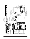
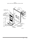
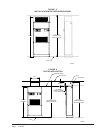
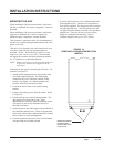
Figure 1 Unit Dimensions ..................................... 6
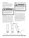
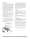
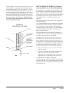
Figure 2 Removal of Unit From Skid .................... 7
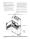
Figure 3 Proper Handling of Unit After Removal
from Skid................................................ 8
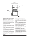
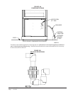
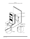
Figure 4 Installation of Unit w/Wall Sleeve .......... 9
Figure 5 Installation With Free Blow Plenum ..... 10
Figure 6 Ducted Application ............................... 10
Figure 7 Supply Duct Connections ..................... 11
Figure 8A Condensate Drain ................................ 12
Figure 8B Optional Rear Drain ............................. 12
Figure 8C Rear Drain (Top View) .......................... 13
Figure 9 Removal of Q-T
EC ERV ........................ 14
Figure 10 Remove Locking Screws from Wheels 15
Figure 11 Unit Mounting Without Wall Sleeve ..... 16
Figure 12 Component Location ............................ 17
Figure 13 Low Voltage Wire Harness Plug .......... 19
Figure 14 Remote Thermostat Wiring "X" Option 20
Figure 15 Remote Thermostat Wiring "D" Option 21
Figure 16 Remote Thermostat Wiring "H" Option 22
Figure 17 Fluid Connections w/Ventilation
Wall Sleeve .......................................... 26
Figure 18 Fluid Connections w/o Ventilation
Wall Sleeve .......................................... 27
Figure 19 Circulation System ............................... 30
Figure 20 Water Temperature and Pressure
Test Procedure .................................. 31
Figure 21 Performance Model WGPM-1C ........... 32
Figure 22 Performance Model WGPM-2C ........... 32
Figure 23 Piping Diagram .................................... 33
Figure 24 Cleaning Water Coil ............................. 36
Figure 25 Water Well System .............................. 37
Figure 26 Water Source H/P Cooling Cycle ......... 39
Figure 27 Water Source H/P Heating Cycle ........ 40
Figure 28 Control Disassembly ............................ 43
Figure 29 Winding Test ........................................ 43
Figure 30 Drip Loop ............................................. 43
Tables
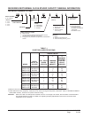
Table 1 Electrical Specifications ........................... 5
Table 2 Operating Voltage Range ....................... 18
Table 3 Wall Thermostats ................................... 18
Table 4 Indoor Blower Performance ................... 25
Table 5 Pressures ............................................... 28
Table 6 Optional Accessories ............................. 29
Table 7 Constant Flow Valves............................. 33
Table 8 Water Flow and Pressure Drop .............. 38
CONTENTS