


Manual 2100-532B
Page 15 of 46
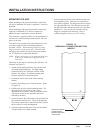
INSTALLATION INSTRUCTIONS
MOUNTING THE UNIT
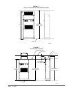
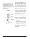
When installing a QW unit near an interior wall on the
left side, a minimum of 8 inches is required; 12 inches is
preferred.
When installing a QW unit near an interior wall on the
right side, a minimum of 12 inches is required as
additional space is required to connect the drain.
This clearance is required to allow for the attachment of
the unit to the wall mounting brackets and the side trim
pieces to the wall.
This unit is to be secured to the wall when there is not a
vent sleeve used with the wall mounting brackets
provided. (NOTE: Wall mounting brackets are only
shipped on units with no vent inside.) The unit itself,
the supply duct, and the free blow plenum are suitable
for “0” clearance to combustible material.
NOTE: When a wall sleeve is to be used attach the unit
to the sleeve with bracket supplied with the
wall sleeve.
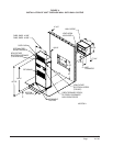
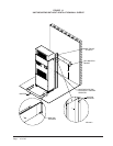
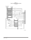
Following are the steps for mounting the QW units. For
reference see Figure 11.
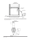
1. Attach wall mounting bracket to the structure wall
with field supplied lag bolts. The fluid piping
connections are to be within the confines of this
bracket. See Figure 1 for cabinet openings and
location of fluid coil connection points.
2. Position the unit in front of the wall mounting
bracket.
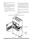
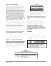
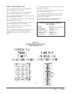
3. Remove the locking screws from the wheels. Refer
to Figure 10.
4. Roll the unit up to the wall mounting bracket. The
unit must be level from side to side. If any
adjustments are necessary, shim up under the rollers
with sheets of steel or any substance that is not
affected by moisture.
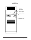
5. Secure the unit to the wall bracket with provided #10
hex head sheet metal screws. There are prepunched
holes in the cabinet sides, and the bracket has slotted
holes to allow for some misalignment.
6. Position the bottom trim piece to the unit and attach
with provided screws (dark colored).
7. Position side trim pieces to the wall and attach with
field supplied screws. There are two long and two
short pieces supplied. The long pieces are to enclose
the gap behind the unit. The short pieces are to fill
the gap behind the cabinet extension or the free blow
plenum box. They may be cut to suit the ceiling
height or overlap the unit side trim. There is
sufficient length to trim up to a 10'2" ceiling.
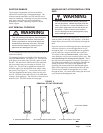
FIGURE 10
REMOVING LOCKING SCREWS FROM
WHEELS
REMOVE SCREWS
FROM WHEELS
BEFORE ROLLING
INTO PLACE