


Manual 2100-532B
Page 11 of 46
DUCT WORK
Any heat pump is more critical of proper operating
charge and an adequate duct system than a straight air
conditioning unit. All duct work must be properly sized
for the design airflow requirement of the equipment.
Air Conditioning Contractors of America (ACCA) is an
excellent guide to proper sizing. All duct work or
portions thereof not in the conditioned space should be
properly insulated in order to both conserve energy and
prevent condensation or moisture damage. When duct
runs through unheated spaces, it should be insulated
with a minimum of one inch of insulation. Use
insulation with a vapor barrier on the outside of the
insulation. Flexible joints should be used to connect the
duct work to the equipment in order to keep the noise
transmission to a minimum.
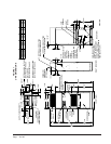
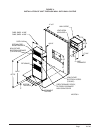
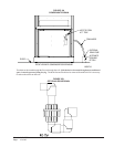
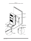
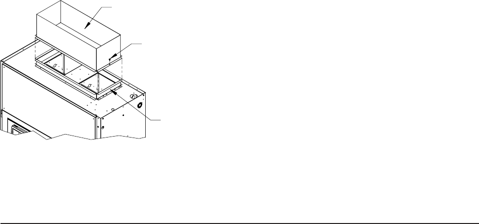
The Q-Tec Series heat pump has provision to attach a
supply air duct to the top of the unit. Duct connection
size is 12 inches x 20 inches. The duct work is field
supplied and must be attached in a manner to allow for
ease of removal when it becomes necessary to slide the
unit out from the wall for service. See Figure 7 for
suggested attachment method.
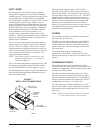
NOTE: Unit cabinet, supply air duct and free blow
plenum are approved for “0” clearance to
combustible material.
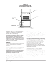
The Q-Tec Series heat pumps are designed for use with
free return (non-ducted) and either free blow with the
use of QPB Plenum Box or a duct supply air system.
The QPB Plenum Box mounts on top of the unit and has
both vertically and horizontally adjustable louvers on
the front discharge grille.
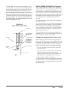
When used with a ducted supply, a QCX Cabinet
Extension can be used to conceal the duct work above
the unit to the ceiling. This extends 20" above the unit
for a total height above the floor of 10'-7/8". The unit is
equipped with a variable speed indoor blower motor
which increases in speed with an increase in duct static
pressure. The unit will therefore deliver proper rated
airflow up to the Maximum ESP shown in Table 4.
However, for quiet operation of the air system, the duct
static should be kept as low as practical, within the
guidelines of good duct design.
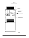
FILTERS
Two 2-inch pleated filters are supplied with each unit.
The filters fit into a fixed rack.
The filters are serviced from the inside of the building .
To gain access to the filters release the latch on the
circuit breaker door and one 1/4 turn fastener near the
bottom of the door. This door is hinged on the left so it
will swing open.
The internal filter brackets are adjustable to
accommodate 1-inch filters. The tabs for the 1-inch
filters must be bent up to allow the 1-inch filters to slide
in place.
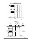
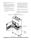
CONDENSATE DRAIN
The condensate drain hose is routed down from the
evaporator drain pan on the right side of the unit into the
compressor compartment. There are three locations that
the drain can exit the cabinet.
If the drain is to be hard plumbed, there is a 3/4 inch
FPT pipe connection located on the cabinet rear panel.
In these installations, the drain tube is to be slipped over
the pipe connection inside of the cabinet; this is how it
is shipped from the factory. (See Figure 8C.)
For a stand pipe type of drain, the drain hose can exit
the rear of the cabinet. There is adequate hose length to
reach the floor on the right hand side of the unit. (See
Figure 8A.)
NOTE: Whichever type of drain connection is used a
“P” trap must be formed. See Figure 8A.
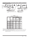
FIGURE 7
SUPPLY DUCT CONNECTIONS
OF QW UNIT
ROOM SIDE
DUCT FLANGE
PROVIDED WITH UNIT
SUPPLY DUCT TO
BE FIELD SUPPLIED
ATTACHMENT
SCREWS TO
BE FIELD
SUPPLIED
MIS-2742