


Manual 2100-532B
Page 24 of 46
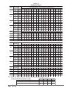
OPTIONAL CFM
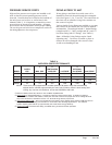
All models covered by this Manual are factory set to
operate at rated CFM levels as shown in Table 4. Rated
CFM is required for ducted applications for maximum
performance ratings.
For free blow applications where Full Load Rated CFM
is undesirable due to sound levels, there is an optional
CFM that can be obtained (-10%). This CFM level will
reduce the system capacity performance by
approximately 2% at the same energy efficiency.
For Full Load Optional CFM:
1. Disconnect all power to the unit. Failure to do so
may result in damage to the motor.
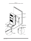
2. Open hinged return air grille service panel.
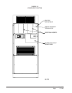
3. Open control panel cover.
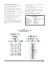
4. Locate low voltage terminal strip and purple wire
with white trace that connects to terminal “Y2”.
Disconnect this wire from terminal “Y2” and tape
off end.
5. Reverse steps to reassemble.
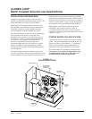
IMPORTANT INSTALLER NOTE
For improved start up performance, wash the indoor coil
with dishwashing detergent.
PHASE MONITOR
All units with three phase scroll compressors are
equipped with a three phase line monitor to prevent
compressor damage due to phase reversal.
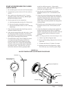
The phase monitor in this unit is equipped with two
LEDs. If the Y signal is present at the phase monitor
and phases are correct, the green LED will light and
contactor will energize. If phases are reversed, the red
fault LED will be lit and compressor operation is
inhibited.
If a fault condition occurs, reverse two of the supply
leads to the unit. Do not reverse any of the unit factory
wires as damage may occur.
SERVICE HINTS
1. Caution user to maintain clean air filters at all times.
Also, not to needlessly close off supply air registers.
This may reduce airflow through the system which
shortens equipment service life as well as increasing
operating costs and noise levels.
2. Check all power fuses or circuit breakers to be sure
that they are the correct rating.
3. The heat pump wall thermostats perform multiple
functions. Be sure that all function switches are
correctly set for the desired operating mode before
trying to diagnose any reported service problems.
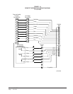
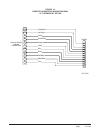
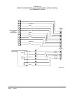
SEQUENCE OF OPERATION
COOLING – A 24V solenoid coil on the reversing
valve controls the cooling cycle operation. There are
two different thermostat options. 1.) Allows for “Auto”
changeover from cycle to cycle. 2.) The other (Manual
changeover). The Auto changeover mode will cause the
reversing valve solenoid to cycle with each cooling call
and may cause a “swooshing sound” with refrigerant
equalization at the end of each cycle.
On a call for Part Load Cooling by the thermostat, it
completes a circuit from “R” to “Y1”, “O” and “G” for part
load cooling. “Y1” starts the compressor, “O” energizes
the reversing valve and “G” starts the indoor blower.
On a call for Full Load Cooling by the thermostat, it
completes the same as Part Load Cooling above, but also
includes a signal to “Y2”. Signal “Y2” energizes the staging
solenoid on the side of the compressor and the signal also
goes to the indoor blower to ramp-up the airflow.
HEATING – On a call for Part Load Heating by the
thermostat, it completes a circuit from “R” to “Y1” and
“G”. “Y1” starts the compressor and “G” starts the
indoor blower.
On a call for Full Load Heating by the thermostat, it
completes the same as Part Load Heating above, but also
includes a signal to “Y2”. Signal “Y2” energizes the staging
solenoid on the side of the compressor and the signal also
goes to the indoor blower to ramp-up the airflow.
DELAY ON MAKE TIMING
setunim50
.
)sdnoces03(BOD= MODsdnoces321
setunim0.
1
)sdnoces06(BOD= MODsdnoces621
setunim0.2)sdnoceS021(BOD= MODsdnoces231
setunim0.3)sdnoces081(BOD= MODsdnoces831
setunim0.4)sdnoces042(BOD=
MO
Dsdnoces441
setunim0.5)sdnoces003(BOD= MODsdnoces051