


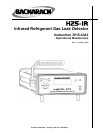

H25-IR Introduction
Instruction 3015-4342 5
1.6 Functional Overview
The H25-IR is an industrial gas leak analyzer for the detection of CFCs, HCFCs, HFCs and halogen gas
compounds, R600a, SF
6
, CO
2
or R227. This instrument can be used to locate and then quantify gas leaks,
as well as log and totalize a group of leaks in a system.
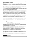
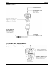
The H25-IR’s front panel contains 7 membrane pushbuttons, probe connector, calibration gas port, and a
3-¼ x ¾ inch VFD (Vacuum Fluorescent Display) that provides a bright, high-contrast display for easy
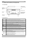
viewing. The instrument is housed in an all-metal case with adjustable handle.
The instrument has two modes of operation: Search and Measure. The Search mode is used to locate the
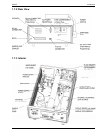
source of a leak. While the Measure mode is used to quantify the size of the leak. A hand-held probe is
used to draw in a gas sample from the area under inspection.
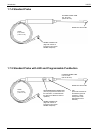
With the instrument in its Search mode, the location of a leak is pinpointed by means of visual and audio
indicators positioned on both the instrument and probe*. As the probe tip approaches the leak source the
length of a bar graph at the bottom of the instrument’s front panel display, the blink rate of an LED on the
probe, and the frequency of an audible tone are all affected in a positive manner (bar graph becomes
longer, LED flashes faster, and the audio tone increases in frequency). There are three search sensitivities
available: SM, MED and LG, indicating the size of the leak being searched for. This feature is useful in
avoiding being bothered with small leaks when searching for larger ones.
In the Measure mode, the probe tip is held over the leak source until the displayed value of the leak rate
stabilizes. Leak rates can be displayed in units of Oz/yr, g/yr, mL/s, PaM
3
/s. The Measure mode can also
be used to display the quantity of gas contained in a confined space with the instrument set up in its
ppm mode.
The leak rate is measured by first capturing all the gas leaking from the component under test. Then by
accurately measuring the flow rate of the sampling stream and the gas concentration within that stream,
the leak rate can be calculated using Equation 1-1. The instrument then converts this data into the
desired leak rate units of measure and displays the leak rate on the instrument’s front panel.
Leak Rate = Flow Rate x Gas Concentration Eq. 1-1
where:
Leak Rate = rate of gas leak from component under test
Flow Rate = sample flow rate
Gas Concentration = concentration of gas in the sample (ppm)
A leak measurement can be logged in memory with a time/date stamp. Up to 50 leaks can be logged and
totalized. This feature is useful in testing an installation that has a maximum permissible leak rate.
Logged data can be recalled for viewing on the display.
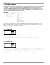
There are four user-defined setups that allow the operator to quickly switch between frequently used
combinations of Gas Type, Range, Feedback Mode, Setpoint, and the Auto Zero Off condition.
Extensive diagnostics keep track of several system parameters. When a fault is detected, the word
“FAULT” blinks on the display and an audible beep is heard every 2 seconds. Text descriptions of all
current fault conditions can be displayed from the instrument’s Diagnostics menu.
Four SPDT relays provide control over a variety of external equipment (e.g., horns, bells, strobe lights)
that can be automatically triggered when their associated relays are energized by any one of 11 different
operating conditions.
A 4−20 mA current loop output can be used for the connection of external monitoring equipment (e.g.,
chart recorder).
* The Standard Probe does not contain an LED.