H25-IR Preparing for Operation
Instruction 3015-4342 19
2.8 4–40 mA Current Loop Connection
An external 4−20 mA monitoring device (e.g., chart recorder) can be connected to the H25-IR using a
shielded-twisted-pair cable.
IMPORTANT! The monitoring device must be isolated from ground (floating).
Locate the 4−20 mA connector on the rear of the unit (refer to Section
1.7.2 Rear View), and then remove
the resistor or shorting wire from its terminals.
NOTE: A 100 ohm, ¼ W resistor must be connected to the 4–20 mA connector if no external monitoring
device is used. Failure to install this resistor will cause a “Loop Open Error” to occur (refer to Section “
4.3
What to Do when a Fault Occurs”).
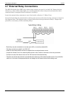
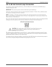
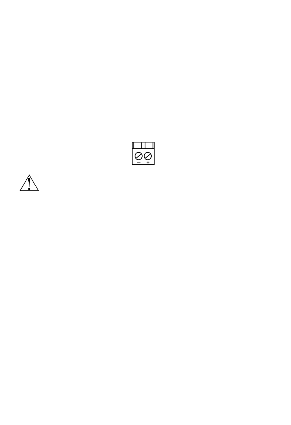
Secure the wire leads from the external monitoring device to the connector as shown in the diagram below,
making sure that the polarity at this connector matches the wiring at the monitoring device.
4–20 mA Current Loop Connector
CAUTION: Never apply power to the 4–20 mA Current Loop Connector from
an external power supply. In addition, connect only a load resistor or a
floating measurement device.
The default current-to-ppm factor is set to 0.016 mA = 1 ppm, providing a measurement range of 0 ppm
(4 mA) to 1,000 ppm (20 mA). Note that the current-to-ppm factor can be changed using the instrument’s
LOOP function (refer to Section
2.4.4 4–20 mA Loop).
To facilitate loop zero and span checking, note that when the LOOP function is selected the loop output is
set to 20 mA, and upon exiting this function the loop output is set to 4 mA.


