


H25-IR Operation
Instruction 3015-4342 29
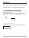
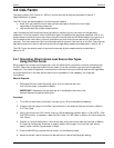
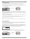
Gas Measurement
Leak Units
Gas Type Mode
Setup Name (first 8 characters)
Range & Mode
Graphical Display of Gas Level
4 Operation
4.1 Instrument Location
The H25-IR Refrigerant Gas Leak Detector should be placed on a flat, horizontal surface such as a bench
or table top when in use.
When searching for leaks, the instrument does not need to be in a gas-free area. This is because of the
instrument’s ability to automatically zero-out background gases and still be able to locate gas leaks.
When making leak-rate measurements, the instrument needs a location where the air is clean and free of
the gas being monitored − this is necessary for zeroing purposes. If the area is contaminated, then a fresh-
air source (e.g., fresh air piped in from the outside) must be made available so the operator can manually
zero the instrument before making a measurement.
4.2 Using the H25-IR
4.2.1 Power
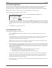
Plug the instrument into the nearest AC outlet (100 to 240 VAC, 50/60 Hz), and then set the rear panel
power switch to its ON position. After being turned ON, the instrument requires 120 seconds to warm-up.
A detailed description of the front panel display screens that are shown during turn-on and warm-up is
contained in Section
2.3 Turning ON the Instrument.
4.2.2 Initial Setup
At this time the H25-IR should already be set up as described in Section 2 Preparing for Operation.
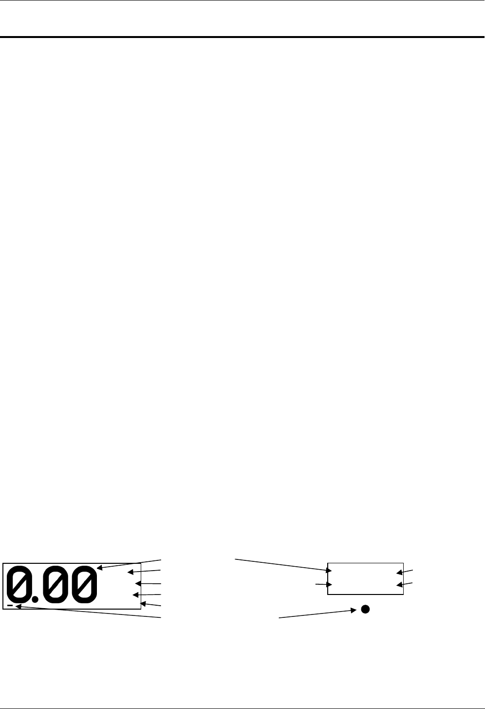
After warming up, the instrument’s Data Display screen will show the current Gas Measurement, Leak
Units, Gas Type, Setup Name, Range, and Mode of Operation. In addition, a graphical display of the
relative gas level is provided by a bar graph at the bottom of the screen whose length increases up the
screen as the gas level increases. An audible tone may also be heard whose pitch increases in frequency as
the gas level increases. Note that the sensitivity of the bar graph and audible tone for any given gas level
is dependent on the Range setting.
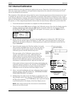
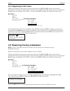
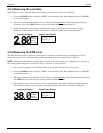
When using the Smart probe, its LCD will show the current Gas Measurement, Range, Mode of Operation,
and Setup Number in parentheses. If the probe contains a red LED, the blink rate of the LED will increase
as the gas level increases. Note that the sensitivity of the LED’s blink rate for any given gas level is
dependent on the Range setting.
Instrument Display Smart Probe Display
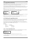
The Leak Units can be changed per Section
2.4.2 Leak Units; the Gas Type changed per Section 2.4.1 Gas
Type; the Setup changed by pressing the SETUP button; the Range changed by pressing the RANGE
button; and the Mode changed by pressing the MODE button. Note that if the Gas Type is changed during
operation, the Setup Name and Number changes to a dash (−), indicating that the previously selected
Setup is no longer valid.
0
.00 S
M
S
RCH (1)
Range
(Setup No.)
Oz/yr
R134A
SETUP
SM SRCH