


Installation
40 Instruction manual SGE
3
is
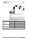
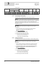
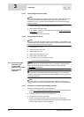
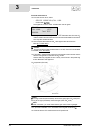
3.12.7 Connecting extra head pump
Note
This pump is essential if a greater head is required. When the system has
such a high resistance (>66 kPa) that the pump in the pump station is
insufficient, you can connect a second (ON/OFF) pump to the solar heating
system controller.
1. Connect earth ( ), live and neutral to terminals 7 through 9.
2. Fit the cable in the strain relief.
3. If you need to connect an extra head pump, continue (3.12.8 "
Connecting
Q/T sensor"); otherwise:
- Fit the covers over the controller.
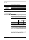
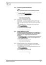
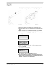
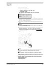
3.12.8 Connecting Q/T sensor
Note
You can optionally add a Q/T sensor to the installation. This enables you to
calculate the energy contribution of the system. For more information or to order
the Q/T sensor, please contact your supplier.
1. Connect the 5V to J12-1.
2. Connect sensor S
4
to J12-2.
3. Connect earth to J12-3.
4. Connect the "flow signal" to J12-4.
5. Fit the cable in the strain relief.
6. If you have no more connections to make:
- Fit the covers over the controller.
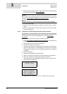
3.13 Check the supply
pressure, gas
control valve
pressure, CO
2
value
and switching
pressure
Note
Before starting to use the appliance and/or checking the supply pressure
and/or the CO
2
value and/or the switching pressure, you should first
fill (5 "Filling") the appliance.
Caution
When starting up for the first time or after conversion, you must always
check the supply pressure, the gas control valve pressure, the CO
2
value and
the switching pressure.
Note
A CO
2
meter and a pressure gauge must be available for checking the
supply pressure, gas control valve pressure, CO
2
value and switching pressure.
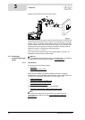
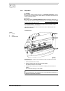
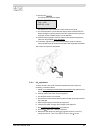
3.13.1 Procedure for checking the supply pressure
To check the supply pressure, proceed as follows:
1. Isolate (10.3 "
Isolating the water heater from the mains") the appliance from
the power supply.
2. Carefully remove the covers from the appliance.
3. The electrical section is now visible.
4. There is a test nipple before the gas control valve (for natural gas
appliances) or before the pressure-reducing valve (for LPG appliances) so
that the supply pressure can be measured.