


Instruction manual SGE 109
is
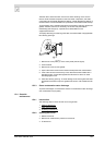
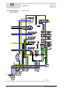
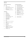
TERMINAL STRIP CONNECTIONS
COMPONENTS
CONTROLLER CONNECTIONS
Earth
N Neutral
L Live input of controller
L
1
Live input of isolating transformer (primary
side)
L
2
Live output of isolating transformer
(secondary side)
L
3
Live input of program-controlled pump
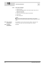
A Control
B Flame probe
C Hot surface igniter
D Gas control valve
E Burner earth connection
F Extra ON mode switch
G Program-controlled pump (max. 100W)
H Extra error signal connection
J Isolating transformer
K Double-pole isolator
L Controller 0/I switch
M Display
NFan
O Temperature sensor (T
2
- bottom of tank)
P Dummy
Q Temperature sensor (T
1
- top of tank)
R Selection resistor
S Push button
T Electrical anodes
U Signalling for electrical anodes
V Potentiostat
W Communication between the appliance
controller and the solar system (BUS
connection)
AA Solar system controller
J2 Power connection for controller
J19 Extra error signal connection
J20 Gas control valve connection
J21 Program-controlled pump connection
J29 Power connection for the fan
J36 Controller display connection
J40 Regulator connection for the fan
JP2 Flame probe and hot surface igniter
connection
JP3 Temperature sensor T
2
connection
JP4 Dummy connection
JP5 Temperature sensor T
1
connection
JP6 Selection resistor and pressure switch
connection
JP8 Extra ON mode switch connection
F1 Fuse (T 3.15A - 250 V)
F3 Fuse (T 3.15A - 250 V)