


Installation
28 Instruction manual SGE
3
is
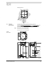
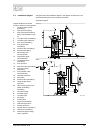
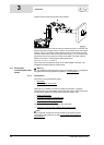
3.8 Gas connection
Warning
The installation should be carried out by a competent person, in compliance
with general and locally applicable regulations (1.3 "Regulations").
Caution
Make sure that the diameter and length of the gas supply pipe are large
enough to supply sufficient capacity to the water heater.
See (D) in the installation diagram (3.5 "Installation diagram").
1. Fit a manual gas valve (10) in the gas supply pipe.
2. Blow the gas pipe clean before use.
3. Close the manual gas valve.
4. Fit the gas supply pipe to the gas control valve.
Warning
After fitting, check for leaks.
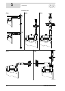
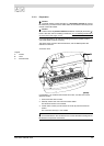
3.9 Solar heating system
Note
Please refer to the installation diagram (3.5 "
Installation diagram"), electrical
diagram (17.4 "
Electrical diagram, solar heating system") and terminal
block (3.12.1 "Preparation") for details of how to connect the solar heating
system.
1. Connect the supply from the solar collector to the inlet (F) of the heat
exchanger.
2. Connect the return pipe to the solar collector to the outlet (G) of the heat
exchanger.
3. Connect the lead to the solar heating system controller and sensor S
2
, see:
- electrical diagram (17.4 "
Electrical diagram, solar heating system")
and
- connections table (3.11.2 "Preparation").
4. Connect the communication cable between the solar heating system
controller and the water heater, see:
- electrical diagram (17.4 "
Electrical diagram, solar heating system")
and
- connections table (3.11.2 "Preparation").
Warning
The installation diagram shows a pump station with an integrated non-return
valve. This type of pump unit may only be used with closed systems. In systems
with drain-back, installation of a pump unit with non-return valve is prohibited.
There are special pump units for these systems. Please contact the pump unit
supplier for this.