


9
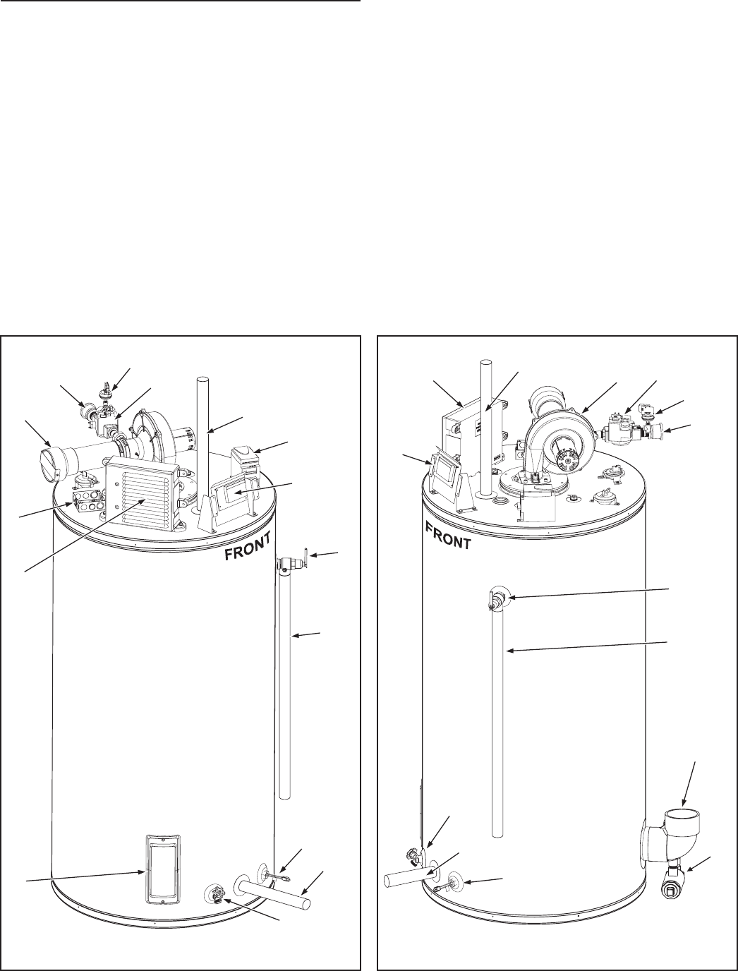
operational buttons. Used to adjust various user settings and
view operational information. See Control System Operation
on page 42.
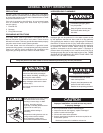
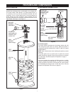
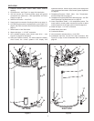
11. Temperature-Pressure Relief Valve. See Temperature-
Pressure Relief Valve on page 15.
12. Temperature-Pressure Relief Valve discharge pipe - see T&P
Valve Discharge Pipe Requirements: on page 15.
13. Lower Temperature Probe, 1 of 2 temperature probes. The
water heater’s control system monitors this probe to detect
water temperature in the lower portion of the storage tank.
14. Water inlet pipe - 1 1/2” NPT connection.
15. Water heater drain valve.
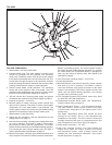
16. Combustion Blower.
17. Vent connection (exhaust elbow) - 4 inch PVC.
18. Condensate trap with 1/2 inch PVC drain connection. See
Figure 9 on page 16 and Condensate Drain Installation on
page 36.
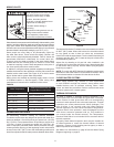
SIDE VIEWS
1. Cleanout access panel, covers water heater cleanout
opening.
2. CCB enclosure - see Figure 3 on page 8 for description.
3. 120 VAC junction box. Incoming power supply and ground
connections are made here - see requirements for Power
Supply on page 13.
4. Intake air connection - 4 inch PVC.
5. Supply gas line connection. See Supply Gas Line on page 13.
6. Low Gas Pressure switch, see description under Figure 3 on
page 8. See Table 4 and the Gas Pressure Requirements on
page 13.
7. Water heater 24 VAC Gas Valve.
8. Water outlet pipe - 1 1/2” NPT connection.
9. VFD (variable frequency drive) blower motor drive - - see
Figure 3 on page 8 for description.
10. UIM (user interface module). The UIM includes the display
circuit board, the control system’s LCD display and
10
8
16
2
7
6
5
11
12
17
18
13
14
15
RIGHT SIDE
11
12
14
15
13
3
2
1
4
5
6
7
8
9
10
LEFT SIDE
Figure 4
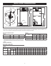
Figure 5