


70
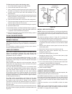
4. See Closed Systems and Thermal Expansion on page 14
5. See Water Line Connections on page 40.
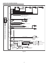
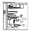
6. If a pump is being installed between a water heater and storage tank or on a building
recirculation loop wire according to Figure 63 on page 66.
7. If a pump is being installed in a recirculation loop between the water heater and a
commercial dishwasher wire according to Figure 63 or Figure 64 on page 66.
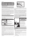
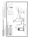
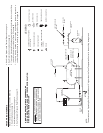
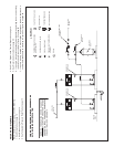
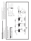
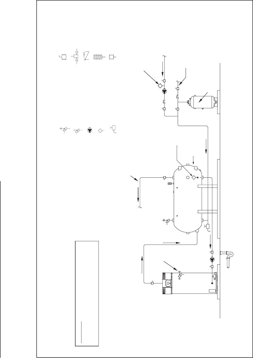
WATER PIPING DIAGRAMS
Before installation of water piping review the following:
1. See Mixing Valves on page 14.
2. See Dishwashing Machines on page 14.
3. See Temperature-Pressure Relief Valve on page 15.
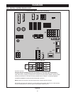
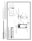
ONE WATER HEATER, SINGLE TEMPERATURE
WITH HORIZONTAL STORAGE TANK FORCED RECIRCULATION
WITH BUILDING RECIRCULATION
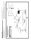
LEGEND
TEMPERATURE & PRESSURE
RELIEF VALVE
PRESSURE RELIEF VALVE
CIRCULATING PUMP
DRAIN
FULL PORT BALL VALV
E
TEMPERATURE GAGE
WATER FLOW SWITCH
CHECK VALVE
MIXING VALVE
WARNING: THIS DRAWING SHOWS SUGGESTED
PIPING CONFIGURATION AND OTHER DEVICES;
CHECK WITH LOCAL CODES AND ORDINANCES
FOR ADDITIONAL REQUIREMENTS.
FINISHED
FLOOR
HOT WATER
OUTLET
ALTERNATE TANK
TEMPERATURE
CONTROL LOCATION
EXPANSION
TANK
HOT WATER
RETURN
COLD WATER
SUPPLY
PIPE T&P TO
OPEN DRAIN
LINE TEMPERATURE
CONTROL
TANK TEMPERATURE
CONTROL
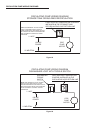
NOTE:
The water heater’s Operating Set Point should be set 5° higher than the Tank Temperature Control in the auxiliary storage tank.
TANK OR LINE TEMPERATURE
CONTROL
AMERICAN
STORAGE TANK