


46
TEMPERATURES MENU (CONT)
DESCRIPTION/ACTION DISPLAY
• Tank Temperature - non adjustable - control system
sensed temperature (averaged from upper and lower
temperature probes).
• Upper Temperature - non adjustable - control system
sensed temperature from the Upper Temperature Probe.
• Lower Temperature - non adjustable - control system
sensed temperature from the Lower Temperature Probe.
• (Heater Regulated to Tank) - non adjustable -
conguration information.
• Upper Probe & Lower Probe Offset - adjustable user
setting, range -5° to +5° (factory setting 0°).
NOTE: These settings should only be used if the hot water
supply temperature varies greatly from the Operating Set
Point setting.
The Upper and Lower Probe Offsets are used to calibrate
control system temperature sensing. This can improve the
precision of temperature control in the storage tank and at
points of use. This feature can also be used to compensate
for building recirculation loops (hot water returning to the
storage tank) that may cause the heating cycles to terminate
prematurely.
Example: If the current sensed temperature from a
temperature probe is 120°F (49°C) and the Offset setting for
that probe is adjusted to a value other than 0°, the control
system would calibrate or “offset” the sensed temperature
from the probe and the averaged tank temperature. Heating
cycles would be activated and deactivated based on the
calibrated (offset) temperature.
These settings are adjusted in the same way described for
the Operating Set Point And Differential Adjustment on page
45.
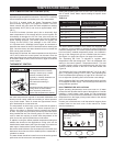
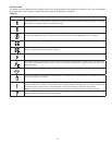
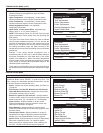
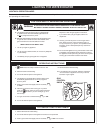
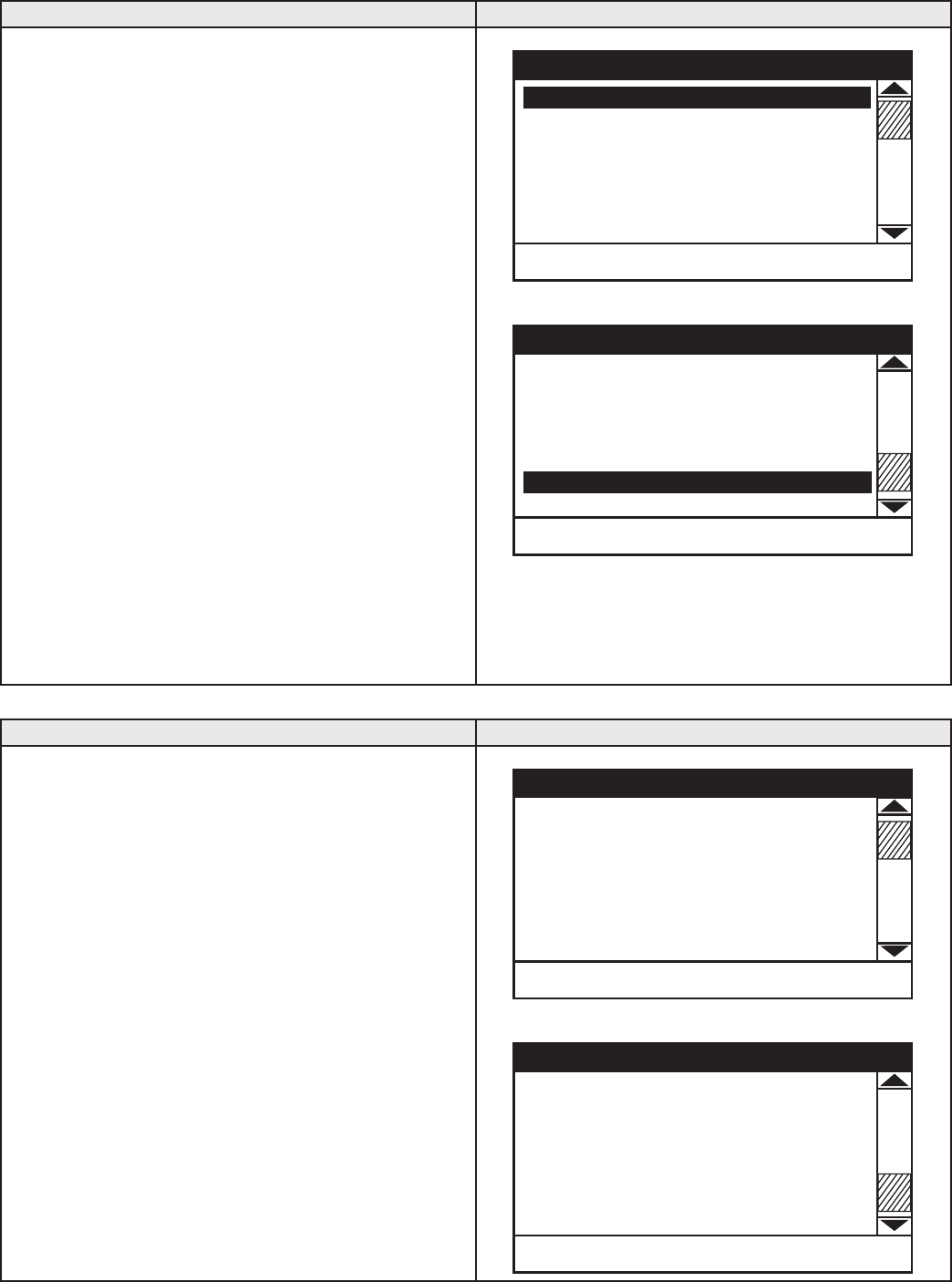
Top of Menu
Operating Set Point 140°F
Differential 8°F
Tank Temperature 120°F
Upper Temperature 122°F
Lower Temperature 118°F
(Heater Regulated to Tank)
Upper Probe Offset 0°F
CHANGE BACK HELP
Temperatures
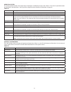
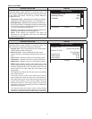
Bottom of Menu
Differential 8°F
Tank Temperature 120°F
Upper Temperature 122°F
Lower Temperature 118°F
(Heater Regulated to Tank)
Upper Probe Offset 0°F
Lower Probe Offset 0°F
CHANGE BACK HELP
Temperatures
HEATER STATUS MENU
DESCRIPTION/ACTION DISPLAY
Select Heater Status from the Main Menu and press the
Operational Button under "SELECT" to enter this menu. This
menu contains non adjustable operational information. Use the
Up & Down Buttons to navigate the menu.
• Status - displays the current Operating State, see Table 12
on page 44.
• ECO Contact, Low Gas PS, Blocked Inlet PS, Blocked
Outlet PS, Blower Prover PS - displays the current state
of the switch contacts; open or closed.
• Blower On, Igniter On, Gas Valve On - displays whether
or not the control system is currently energizing these water
heater components; yes = energized, no = de-energized.
• Igniter Current - displays whether or not the control
system has detected the required minimum current, see
Sequence Of Operation on page 46.
• Flame Detected - displays whether or not the control
system has detected Main Burner ame during ignition from
the ame sensor.
• External Input Enable - displays whether or not the S1
dipswitches have been congured to activate the enable/
disable circuit, see Enable/Disable Circuit on page 39.
• Ignition Trials - displays whether or not the S1 dipswitches
have been congured to allow 1 or 3 trials for ignition
before declaring an "Ignition Failure" Fault condition, see
the CCB - Central Control Board Layout on page 63.
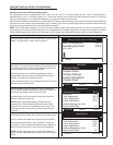
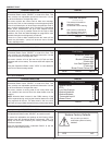
Top of Menu
Status Standby
ECO Contact Closed
Low Gas PS Closed
Blocked Inlet PS Closed
Blocked Outlet PS Closed
Blower Prover PS Open
Blower On No
BACK HELP
Heater Status
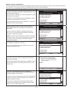
Bottom of Menu
Blower On No
Igniter On No
Igniter Current No
Gas Valve On No
Flame Detected No
External Input Enable No
Ignition Trials 3
BACK HELP
Heater Status