


36
2. The eld installed condensate drain line must not be less
than 1/2 inch PVC in size.
3. DO NOT remove, modify or alter the factory condensate trap.
INSTALLATION INSTRUCTIONS
1. Ensure the water heater’s on/off switch is in the “off” position.
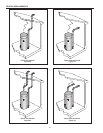
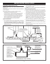
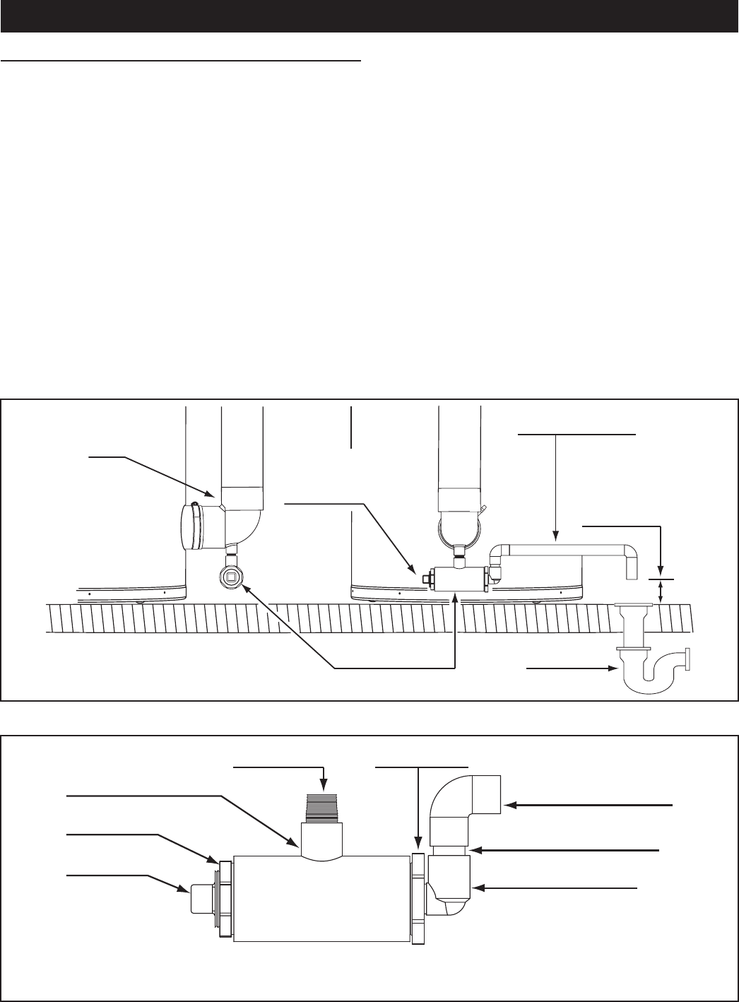
2. Install a 1/2 inch PVC condensate drain line between the
condensate drain connection on the Condensate Drain Trap
and a suitable building drain, see Figure 50 and Figure 51.
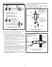
3. Terminate the condensate drain piping with an elbow above
the drain. Ensure that any discharge will exit the condensate
drain line no more than 6 inches (15.2 cm) above a suitable
building drain, or external to the building, see Figure 50.
NOTE: In cold climates it is recommended the condensate
drain be terminated at a suitable drain inside the building.
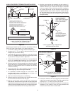
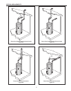
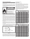
4. Ensure the condensate drain line is not elevated above the
condensate drain connection on the trap, see Figure 51.
5. Brace the condensate drain line with oor mounted standoffs
every three feet.
6. Ensure the condensate drains freely during start up, see
Start Up on page 50.
WATER HEATER INSTALLATION
CONDENSATE DRAIN INSTALLATION
Installation must conform with these instructions and local
building codes.
Condensate neutralizer kits are available. Contact your distributor
or Service Agency.
Field supplied materials required for installation include:
• Approved PVC cement and PVC primer.
• 1/2 inch PVC pipe - minimum length to equal the distance
between the water heater and a suitable building drain.
• 1/2 inch PVC ttings (elbows and couplings) necessary to
install a condensate drain line between the Condensate
Drain Trap Assembly and a suitable building drain.
• Floor mounted standoffs to brace the drain line.
INSTALLATION NOTES
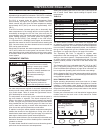
1. The condensate drains from the water heater’s covered by
this instruction have PH levels between 4.3 and 5.0. Install
a commercially available neutralizing kit if required by local
codes. Lower PH levels are acidic. Do not connect a metal
condensate drain line, such as copper pipe, to the water
heater for this reason.
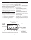
CONDENSATE DRAIN
LINE - FIELD INSTALLED
DRAIN LINE TO
TERMINATE NO
MORE THAN 6
INCHES (15.2 cm)
ABOVE DRAIN
BUILDING
DRAIN
FACTORY INSTALLED
CONDENSATE TRAP
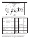
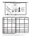
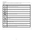
CLEANOUT PLUG SHOULD
FACE TOWARDS THE FRONT
OF THE WATER HEATER FOR
SERVICE ACCESS
EXHAUST (VENT)
ELBOW
CONDENSATE TRAP DETAIL
PVC PIPE PLUG
1 ¼” NPT
CLEANOUT PIPE
PLUG SHOULD
BE ORIENTED TO
THE FRONT OF THE
WATER HEATER FOR
SERVICE ACCESS
PVC BUSHING
1 ½” SLIP x 1 ¼” NPT
PVC BUSHING
1 ½” SLIP x ½” SLIP
PVC TEE FITTING
1 ½” SLIP x 1 ½” SLIP x ½” NPT
PVC PIPE NIPPLE
½” NPT
½” PVC 90° ELBOW
CONDENSATE DRAIN
CONNECTION. FIELD
INSTALLED DRAIN
LINE CONNECTS HERE
½” PVC 90°
STREET ELBOW
½” PVC PIPE NIPPLE
Figure 50
Figure 51