


30
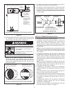
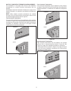
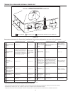
Four Concentric Terminations
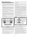
1. When installing four concentric terminations through a roof or
through a sidewall in close proximity they may be arranged
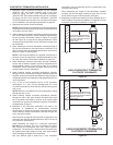
into stacked rows of two as shown in Figure 34 or lateral rows
of two as shown in Figure 35.
2. Four is the maximum number of concentric terminations that
may be installed in a group where all terminations are in
close proximity as shown in Figure 34.
A
A
A = 0 - 2 INCHES (0 - 5 cm)
CLOSE PROXIMITY
CONCENTRIC
TERMINATION
CAPS END VIEW
FOUR CONCENTRIC TERMINATIONS
(THROUGH A ROOF OR SIDEWALL)
Figure 34
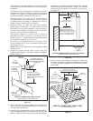
A B
A
FOUR CONCENTRIC TERMINATIONS
(THROUGH A ROOF OR SIDEWALL)
A = 0 - 2 INCHES (0 - 5 cm)
CLOSE PROXIMITY
B = 24 INCHES (61 cm)
OR GREATER
CONCENTRIC
TERMINATION
CAPS END VIEW
Figure 35
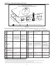
Groups Of Terminations
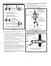
1. When installing multiple groups of concentric terminations
through a roof or through a sidewall in close proximity they
can be installed into stacked groups of four as shown in
Figure 36. Lateral groups of four as shown in Figure 35 may
be a more convenient installation arrangement for multiple
groups depending on available space.
A
A B
A = 0 - 2 INCHES (0 - 5 cm)
CLOSE PROXIMITY
CONCENTRIC
TERMINATION
CAPS END VIEW
EIGHT CONCENTRIC TERMINATIONS
(THROUGH A ROOF OR SIDEWALL)
B = 24 INCHES (61 cm)
OR GREATER BETWEEN
GROUPS OF FOUR
Figure 36
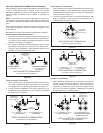
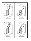
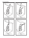
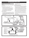
MULTIPLE CONCENTRIC TERMINATION CLEARANCES
When installing multiple concentric terminations vertically through
a roof or horizontally through a sidewall ensure the required
clearances (separation) between terminations are maintained.
Ensure multiple terminations are arranged or grouped as
required.
NOTE: These clearances must be maintained to prevent the
recirculation of vent (exhaust) gases to the intake air. Clearances
are measured between the edges of the concentric termination
caps.
When installing multiple concentric terminations through a roof
or through a sidewall the clearances shown in Figure 32 must
be maintained.
See Multiple Concentric Termination Arrangements on page 31.
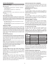
Close Proximity & Standard Clearance
1. The clearance between multiple termination caps must be 0
inches (touching) to a maximum of 2 inches (5 cm), dimension
A - Figure 32, when installing concentric terminations in close
proximity. See Figure 37 on page 31.
2. The clearance between multiple termination caps must be
increased to a minimum of 24 inches (61 cm), dimension B -
Figure 32, when installation in close proximity (above) is not
possible. This is the standard clearance.
A
OR
B
A = 0 - 2 INCHES (0 - 5 cm)
CONCENTRIC
TERMINATION CAPS
END VIEW
TWO CONCENTRIC TERMINATIONS
(THROUGH A ROOF OR SIDEWALL)
B = 24 INCHES (61 cm)
OR GREATER
CLOSE PROXIMITY STANDARD CLEARANCE
Figure 32
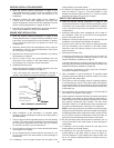
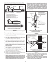
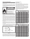
Three Concentric Terminations
1. When installing three concentric terminations through a roof
or through a sidewall the third termination may be installed
in close proximity as indicated by dimension A in Figure 33.
2. If close proximity installation of the third termination is not
possible the third termination may be installed as indicated
by dimension B in Figure 33.
A = 0 - 2 INCHES (0 - 5 cm)
CLOSE PROXIMITY
CONCENTRIC
TERMINATION
CAPS END VIEW
THIRD
TERMINATION
THREE CONCENTRIC TERMINATIONS
(THROUGH A ROOF OR SIDEWALL)
A
A B
B = 24 INCHES (61 cm)
OR GREATER
Figure 33