


29
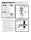
11. Push the vent cap/vent pipe assembly into the intake air Y
tting assembly until the vent cap seats properly on the large
diameter intake air pipe. Ensure the vent pipe is cemented
to the no stop-lip reducer bushing previously installed in
the Y tting. Secure the vent cap to intake air pipe with eld
supplied stainless steel screws. Install the screws through
the pre-drilled holes in the vent cap brackets. Pilot holes for
the screws must be drilled in the intake air pipe to prevent
damage/cracking.
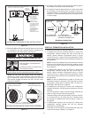
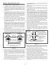
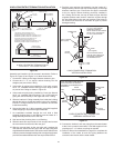
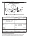
NOTE: SECURING STRAP
MUST BE FIELD INSTALLED
TO PREVENT MOVEMENT
OF TERMINATION KIT
MAINTAIN 12” (30 cm)
18” (45 cm) FOR CANADA
MINIMUM CLEARANCE
ABOVE HIGHEST ANTICIPATED
SNOW LEVEL. MAXIMUM OF
24” (60 cm) ABOVE ROOF.
ROOF FLASHING
(field supplied)
STRAP
(field supplied)
VENT
PIPE
INTAKE
AIR PIPE
COMBUSTION
AIR
VENT
6 INCH CONCENTRIC TERMINATION
VERTICAL INSTALLATION
Figure 30
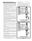
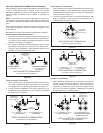
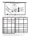
NOTE: SECURING STRAP MUST BE
FIELD INSTALLED TO PREVENT
MOVEMENT OF TERMINATION KIT
IN SIDEWALL.
STRAP
(field supplied)
VENT
PIPE
INTAKE
AIR PIPE
COMBUSTION
AIR
VENT
1 INCH
MAXIMUM
6 INCH CONCENTRIC TERMINATION
SIDEWALL INSTALLATION
Figure 31
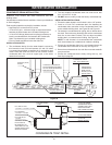
12. Connect the intake air and vent piping from the water heater
to the 6 inch concentric termination. Use eld supplied 4 inch
couplings or 6” x 4” reducer couplings as needed.
13. Return to Direct Vent Installation on page 23 to complete the
installation of the intake air and vent piping between the
concentric termination and the water heater.
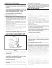
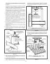
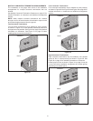
6 INCH CONCENTRIC TERMINATION INSTALLATION
6 INCH CONCENTRIC TERMINATION KIT
SEVEN PIECE KIT - FIELD ASSEMBLY REQUIRED
VENT PIPE
VENT PIPE IS 4 INCH SCHEDULE 40 PVC
SUPPLIED LENGTH 46 1/2 INCHES (118 cm)
MAXIMUM ALLOWABLE LENGTH 66 1/2 INCHES (169 cm)
MINIMUM ALLOWABLE LENGTH 33 1/8 INCHES (84 cm)
INTAKE AIR PIPE IS 6 INCH SCHEDULE 40 PVC
SUPPLIED LENGTH 25 3/8 INCHES (64 cm)
MAXIMUM ALLOWABLE LENGTH 45 3/8 INCHES (115 cm)
MINIMUM ALLOWABLE LENGTH 12 INCHES (30 cm)
VENT CAP
STAINLESS STEEL
VENT TERMINAL
WITH SCREEN
INTAKE AIR PIPE
INTAKE AIR CONNECTION
6” or 4” PVC
VENT
CONNECTION
4” PVC
6” x 4” STANDARD
REDUCER BUSHING
6” x 6” x 6”
Y FITTING
6” x 4” NO STOP-LIP
REDUCER BUSHING
INTAKE AIR PIPE
Y FITTING ASSEMBLY
VENT CAP
VENT PIPE ASSEMBLY
Figure 29
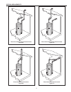
Assemble and install the 6 inch concentric termination. Refer to
Figure 29, Figure 30 and Figure 31 for these instructions:
1. Cement the Y tting to the larger diameter intake air pipe.
2. Cement the 6” x 4” no stop-lip reducer bushing into the
straight (vent) end of the Y tting.
3. If the intake air piping being installed is 4 inch pipe, cement
the 6” x 4” standard reducer bushing into the angle (intake
air) end of the Y tting as shown in Figure 29.
4. If the intake air piping being installed is 6 inch pipe discard
the 6” x 4” standard reducer bushing. The 6 inch intake air
piping will connect directly to the angle end of the Y tting.
5. Slide the intake air Y tting assembly from inside the building
through the hole cut for the termination in the roof or sidewall.
Ensure no foreign materials such as insulation accumulate
inside the assembly.
6. Secure the intake air Y tting assembly using eld supplied
metal strapping or equivalent support materials.
7. On installations installed through the roof slide a eld
supplied plumbing boot or roof ashing over the intake air Y
tting assembly and secure it to the roof.
8. Seal around the plumbing boot or roof ashing.
9. Slide the steel vent cap onto the 4 inch vent pipe and cement
the vent terminal to the end of the vent pipe.
10. Slide the vent cap back up the vent pipe until it touches the
vent terminal. Secure the vent cap to the vent pipe using eld
supplied stainless steel screws. Pilot holes must be drilled for the
screws to prevent damage/cracking of the vent pipe. Apply water
proof silicone sealant between the vent cap and the terminal.