


7
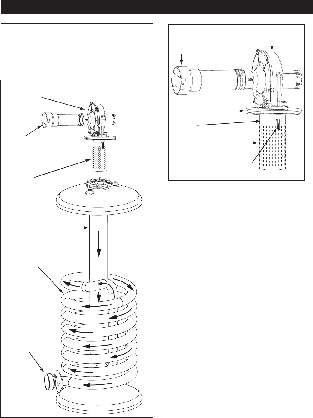
BASIC OPERATION
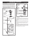
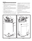
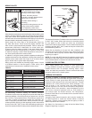
The water heaters covered in this manual have a helical coil
shaped heat exchanger that is submerged in the storage tank.
The water heater’s Main Burner is a radial design burner, it
is mounted on the top and res downward through the heat
exchanger. This is a forced draft burner; hot burning gases are
forced through the heat exchanger under pressure and exit
through the exhaust/vent connection located at the bottom of the
water heater. See Figure 1 and Figure 2.
FEATURES AND COMPONENTS
BLOWER
BURNER
ASSEMBLY
MAIN
BURNER
(radial design)
HEAT
EXCHANGER
INTAKE AIR
(combustion air)
CONNECTION
4 INCH PVC
HELICAL
COIL
VENT (exhaust)
OUTLET
Figure 1
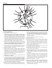
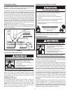
BLOWER/BURNER ASSEMBLY DETAIL
HOT SURFACE
IGNITER
COMBUSTION
BLOWER
FLAME
SENSOR
MAIN
BURNER
(radial design)
BLOWER
FLANGE
INTAKE AIR
(combustion air)
CONNECTION
4 INCH PVC
Figure 2
Hot Surface Igniter
The control system energizes the Hot Surface Igniter with 120
VAC during the igniter warm up period. When the igniter is
energized it produces sufcient heat, >1800°F (>982°C), to ignite
the Main Burner.
NOTE: Care must be taken when handling the igniter to prevent
breakage.
During the igniter warm up period prior to ignition the control
system monitors the igniter current and must sense a minimum
of 2.0 AC amps. See the Sequence Of Operation on page 7.
Flame Sensor
The control system also monitors the ame sensor to conrm
a ame is present at the Main Burner. If a ame is not veried
during the ignition trial period (3-5 seconds) the control system
will immediately de-energize the 24 VAC Gas Valve. See the
Sequence Of Operation Flow Chart on page 55.