


38
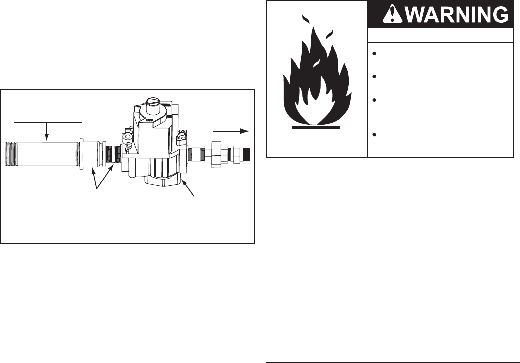
GAS LINE CONNECTION
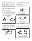
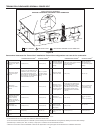
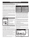
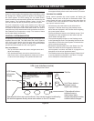
1. v The water heaters covered by this manual are shipped
from the factory with a 1 1/4” supply gas connection, see
Table 1 on page 10. Short pipe nipples and reducer couplings
are factory installed to increase the size of the water heater’s
24 VAC Gas Valve inlet, see Figure 53.
2. Connect the supply gas line to the water heater's 24 VAC
Gas Valve in accordance with all applicable local and national
code requirements. DO NOT use exible gas piping.
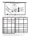
FACTORY INSTALLED
1 1/4” x 1” REDUCER
COUPLING AND NIPPLE
FIELD SUPPLIED
SUPPLY GAS PIPING
1 1/4” NPT MINIMUM
SUPPLY GAS LINE CONNECTION
24 VAC
GAS VALVE
TO MAIN
BURNER
FLOW
Figure 53
3. Apply thread sealing compounds (pipe dope/ Teon tape)
sparingly and only to the male threads of the pipe joints. Do
not apply sealing compound to the rst two threads. Use pipe
dope or Teon tape marked as being resistant to the action of
liquid petroleum (LP/propane) gases.
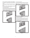
4. Use only a smooth jaw adjustable wrench (such as a monkey
wrench) as a back up on the body of the 24 VAC Gas Valve
when tightening the rst pipe nipple into the body of the valve.
DO NOT use a standard pipe wrench (Stillson wrench) with
metal tooth jaws as this may permanently damage the valve.
5. Use a standard pipe wrench (Stillson wrench) as a back
up on the rst pipe nipple installed above when connecting
other ttings and pipe in the supply gas line to prevent the
24 VAC Gas Valve on the water heater from twisting during
installation.
6. To prevent damage, care must be taken not to apply too
much torque when connecting the supply gas line to the
water heater.
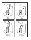
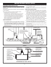
7. Install a sediment trap (dirt leg) as shown in Figure 52 on
page 37.
8. Install a Main Gas Shutoff valve in the supply gas line as
shown in Figure 52 on page 37.
NOTE: Should overheating occur or the gas supply fail to shut
off, turn off the Main Gas Shutoff valve to the water heater.
GAS LINE LEAK TESTING
Fire and Explosion Hazard
Leak test before placing the
water heater in operation.
Disconnect gas piping and main
gas shutoff valve before leak
testing.
Install sediment trap in
accordance with NFPA 54.
Use joint compound or Teflon tape
compatible with propane gas.
Any time work is done on the gas supply system perform a leak
test to avoid the possibility of re or explosion.
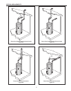
1. For test pressures exceeding 1/2 psi (3.45 kPa) disconnect
the water heater and its Main Gas Shutoff Valve from the gas
supply piping system during testing, see Figure 52 on page 37.
The gas supply line must be capped when disconnected from
the water heater.
2. For test pressures of 1/2 psi (3.45 kpa) or less, the appliance
need not be disconnected, but must be isolated from the supply
gas line by closing the Main Gas Shutoff Valve during testing.
3. Paint all supply gas line joints and connections upstream of
the water heater with a rich soap and water solution to test
for leaks. Bubbles indicate a gas leak. Do not use matches,
candles, ame or other sources of ignition for this purpose.
4. Repair any leaks before placing the water heater in operation.
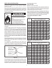
SUPPLY GAS REGULATOR INSTALLATION
The water heaters covered in this manual must have a supply
gas regulator installed in the supply gas line connected to the
water heater. See the Installation Requirements on page 13.
1. A supply gas regulator shall be installed for each water heater
on multiple water heater installations.
2. Supply gas regulators must be rated at or above the input
Btu/hr rating of the water heater they supply.
3. Supply gas regulators shall have inlet and outlet connections
not less than the minimum supply gas line size for the water
heater they supply. See Table 5 on page 13.
The Maxitrol 325-7L supply gas regulator or equivalent is
recommended.
4. Supply gas regulator(s) shall be installed no closer than 3
feet (1 meter) and no farther than 10 feet (3 meters) from the
supply gas connection on the water heater.