


25
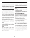
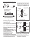
between the eld supplied 90° elbow and the factory supplied
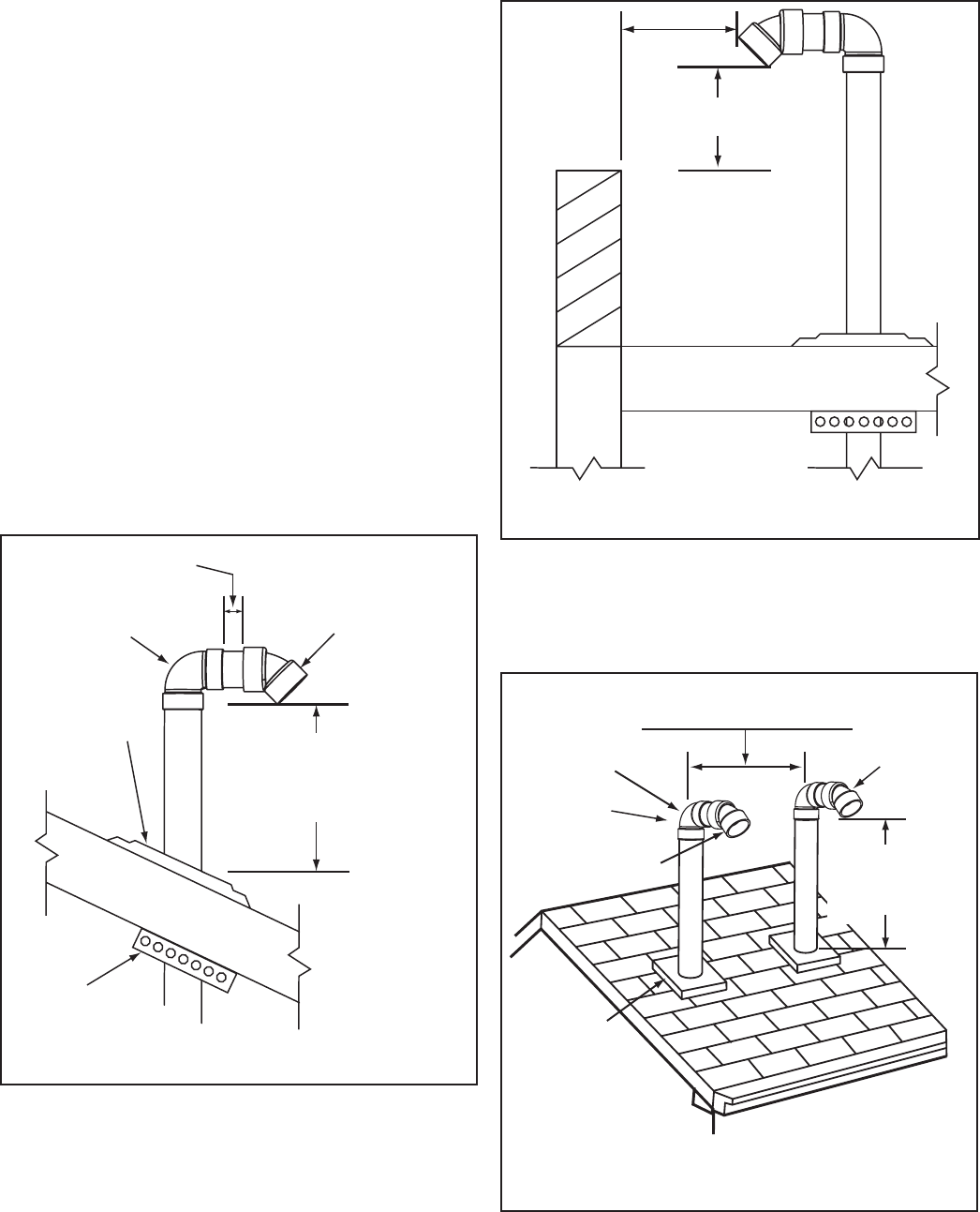
termination must not be excessive in length. The exposed
portion of this pipe shall be no more than 2 inches (5 cm),
see Figure 19.
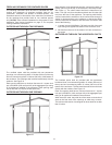
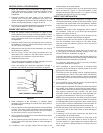
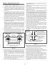
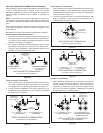
INTAKE AIR AND/OR VENT
TERMINATION(S) MUST BE A
MINIMUM OF 24 INCES (60 cm)
ABOVE ANY PARAPET, VERTICAL
WALL OR STRUCTURE WITHIN
10 FEET (3 m) HORIZONTALLY.
VERTICAL TERMINATION(S) FLAT ROOF CLEARANCE
INTAKE AIR AND/OR VENT (EXHAUST)
24 INCHES (60 cm)
MINIMUM HEIGHT ABOVE
IF LESS THAN
10 FEET (3 m)
Figure 20
11. Return to Power Vent Installation on page 23 or Direct Vent
Installation on page 23 to complete the installation of the intake
air and/or vent piping between the termination(s) and the
water heater.
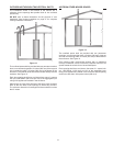
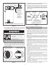
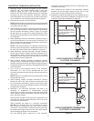
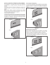
VERTICAL TERMINATION - DIRECT VENT
STANDARD TERMINATIONS
24 INCHES (61 cm) MINIMUM
48 INCHES (122 cm) IN COLDER CLIMATES
FACTORY SUPPLIED
STANDARD TERMINATIONS
POINTED DOWNWARD
FIELD
SUPPLIED
90° ELBOW
VENT (EXHAUST)
TERMINATION
INTAKE AIR
TERMINATION
FIELD SUPPLIED
PLUMBING
ROOF BOOTS
OR FLASHINGS
MAINTAIN 12” (30 cm)
18” (45 cm) FOR CANADA
MINIMUM CLEARANCE
ABOVE HIGHEST
ANTICIPATED SNOW LEVEL.
Figure 21
The intake air and vent terminations must be oriented facing
downward and in the same direction as shown in Figure 21
on page 25.
The intake air and vent terminations must have a minimum
separation of 24” (61 cm) measured on center line as shown
in Figure 21 on page 25. In colder climates this separation
should be increased to at least 48 inches (122 cm).
The bottom edge of the intake air and vent terminations
must be a minimum of 12 inches (30 cm), 18 inches (45 cm)
in Canada, above the average or expected snow level as
shown in Figure 19 and Figure 21 on page 25.
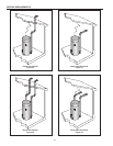
6. When the intake air and/or vent piping from multiple
water heaters will terminate in the same location the vent
terminations can be grouped together in close proximity 0
inches/touching. Intake air terminations can also be grouped
together in close proximity 0 inches/touching.
The distance between the closest vent and intake air
terminations must be a minimum of 24 inches (61 cm) as
shown in Figure 21. In colder climates this separation should
be increased to at least 48 inches (122 cm).
7. Cut a 5 inch (13 cm) diameter hole for 4 inch pipe or 7 inch
(18 cm) diameter hole for 6 inch pipe where the pipe(s) will
pass through the roof.
NOTE: Beware of concealed wiring and piping when cutting
through the roof.
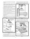
8. Suspend the pipe(s) through center of hole using eld
supplied metal strapping or equivalent support materials as
shown in Figure 19.
2” (5 cm)
MAXIMUM
FACTORY SUPPLIED
STANDARD TERMINATION
POINTED DOWN TOWARDS
THE GROUND
VERTICAL TERMINATION(S) INSTALLATION
INTAKE AIR AND/OR VENT (EXHAUST)
FIELD
SUPPLIED
90° ELBOW
FIELD
SUPPLIED
STRAP/SUPPORT
FIELD SUPPLIED
PLUMBING
ROOF BOOT
OR FLASHING
MAINTAIN 12” (30 cm)
18” (45 cm) FOR CANADA
MINIMUM CLEARANCE
ABOVE HIGHEST ANTICIPATED
SNOW LEVEL.
Figure 19
9. Slide a roof boot or equivalent ashing over the pipe and
secure roof boot or equivalent ashing to roof (see Figure 19)
and seal around the ashing.
10. Install the factory supplied intake air and/or vent termination(s)
using eld supplied pipe and one eld supplied 90° elbow as
shown in Figure 19. The short section of pipe that connects