


24
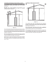
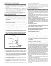
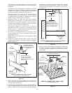
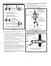
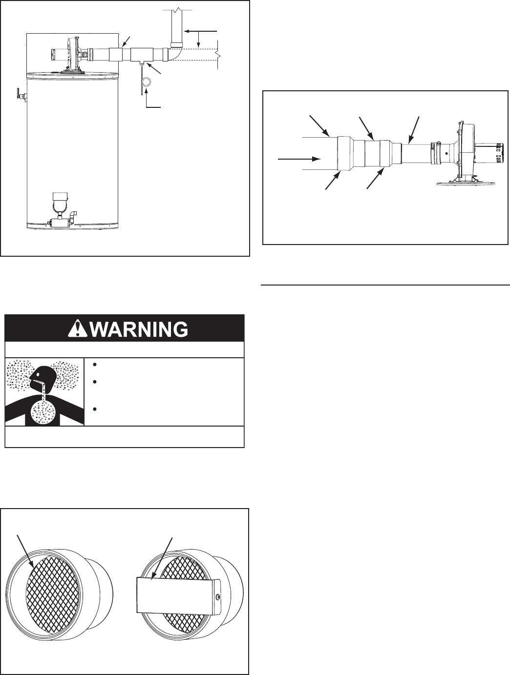
14. If installing 4 inch intake air pipe connect the intake air pipe to
the intake air connection on the water heater.
15. If installing 6” intake air pipe transition to 4” pipe at the intake
air connection on the water heater as shown in Figure 18.
The eld installed 4” pipe between the intake air connection
and the 6” x 4” reducer coupling should be 18 inches (45 cm)
or less in length.
3” PIPE FACTORY
INSTALLED
6” PIPE FIELD
SUPPLIED
4” PIPE FIELD
SUPPLIED
6” x 4” REDUCER
FIELD SUPPLIED
4” x 3” REDUCER
FACTORY INSTALLED
INTAKE AIR CONNECTION
INTAKE AIR CONNECTION
INTAKE AIR
COMBUSTION
BLOWER
Figure 18
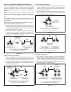
VERTICAL TERMINATION INSTALLATION
1. Determine the location for the termination(s).
2. If installing only the vent (exhaust) piping in a Power Vent
conguration vertically through the roof; ensure that all
exterior vertical clearance requirements shown in Figure
19 and Figure 20 on page 25 are being maintained. These
clearances and those cited by local and national codes must
be maintained.
NOTE: On at roof installations the vent termination must be
a minimum of 24 inches (60 cm) above any parapet, vertical
wall or structure within 10 feet (3 m) horizontally. See Figure
20 on page 25.
3. If installing both intake air and vent piping in a Direct Vent
conguration vertically through the roof; ensure that all
exterior vertical clearance requirements shown in Figure
19 and Figure 20 on page 25 are being maintained. These
clearances and those cited by local and national codes must
be maintained.
NOTE: On at roof installations the intake air and the vent
terminations must be a minimum of 24 inches (60 cm) above
any parapet, vertical wall or structure within 10 feet (3 m)
horizontally. See Figure 20 on page 25.
4. If installing only vent piping in a Power Vent conguration
vertically through the roof the following instructions must be
followed:
The vent termination must be oriented facing downward as
shown in Figure 19 and Figure 20 on page 25.
The bottom edge of the vent termination must be a minimum
of 12 inches (30 cm), 18 inches (45 cm) in Canada, above
the average or expected snow level as shown in Figure 19
on page 25.
5. If installing both intake air and vent piping in a Direct Vent
conguration vertically through the roof the following
instructions must be followed:
The intake air and vent pipes must penetrate the same side
of the roof as shown in Figure 21 on page 25.
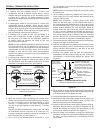
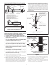
INSTALL TEE FITTING AS CLOSE TO WATER HEATER
INTAKE AIR CONNECTION AS POSSIBLE
INTAKE AIR CONDENSATE TEE INSTALLATION
FIELD SUPPLIED
3” x 3” x 1/2” TEE
WITH HOSE BARB
FITTING INSTALLED
FACTORY
INTAKE AIR
CONNECTION
INTAKE
AIR
PIPING
CONNECT FIELD
SUPPLIED FLEXIBLE
DRAIN HOSE TO BARB
FITTING AND FORM A
LOOP WATER TRAP IN
DRAIN HOSE
RUN DRAIN HOSE
TO SUITABLE FLOOR
DRAIN SEPARATELY
FROM OTHER
CONDENSATE DRAINS
Figure 16
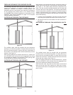
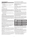
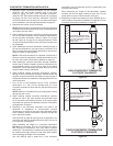
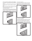
13. Ensure the Balance Plate and Intake Air Screen on the Intake
Air Connection are both removed before connecting the
intake air pipe to the water heater, see Figure 17.
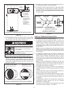
Do not obstruct water heater air intake.
Gas and carbon monoxide detectors
are available.
Install water heater in accordance with
the instruction manual.
Breathing carbon monoxide can cause brain damage or
death. Always read and understand instruction manual.
Breathing Hazard - Carbon Monoxide Gas
NOTE: Do not leave the screen inside the Intake Air
connection in Direct Vent installations. Once the intake air
pipe is installed the screen will be hidden from view and
may become clogged with debris over time. This will cause
improper combustion.
INTAKE AIR BALANCE PLATE AND SCREEN
4” x 3” REDUCER
COUPLING - FACTORY INSTALLED
BALANCE PLATE
(remove for Direct Vent)
INTAKE AIR SCREEN
(remove for Direct Vent)
Figure 17