


26
SIDEWALL TERMINATION INSTALLATION
1. Determine the location for the termination(s).
2. If installing only vent (exhaust) piping in a Power Vent
conguration through a sidewall; ensure that all exterior
sidewall clearance requirements for the termination, shown
in Figure 48 on page 34, are being maintained. These
clearances and those cited by local and national codes must
be maintained.
3. If installing both intake air and vent piping in a Direct Vent
conguration through a sidewall; ensure that all exterior
sidewall clearance requirements for the terminations, shown
in Figure 49 on page 35, for the vent and intake air termination
are being maintained. These clearances and those cited by
local and national codes must be maintained.
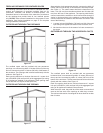
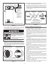
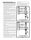
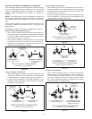
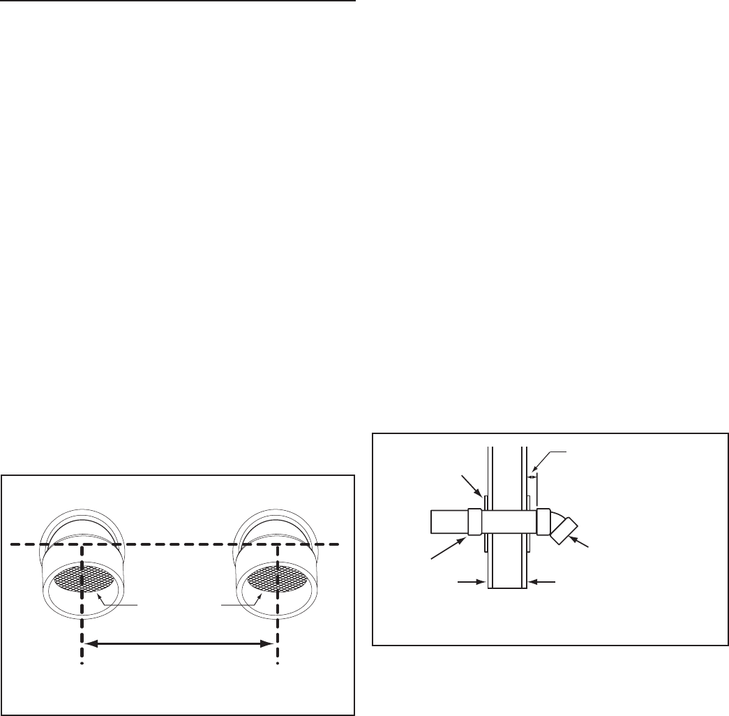
4. If installing both an intake air and vent termination in a
Direct Vent conguration through a sidewall there must
be a minimum of 24 inches (61 cm) separation, measured
on vertical center line, between the intake air and vent
terminations, see Figure 22.
NOTE: In colder climates this separation should be increased
to at least 48 inches (122 cm) between the intake air and
vent termination or any other appliance vent that discharges
moisture-laden air such as clothes dryers. This will reduce
possibility of frost over from side winds blowing exhaust
vapors to the intake air termination and is recommended for
Canadian installations.
5. If installing both intake air and vent terminations in a Direct
Vent conguration through a sidewall the intake air and
vent terminations must be installed at the same elevation
measured on horizontal center line - see Figure 22.
VENT (EXHAUST)
TERMINATION
INTAKE AIR
TERMINATION
INSTALL ON
ELEVATION
CENTERLINE
24 INCHES (61 cm) MINIMUM
48 INCHES (122 cm) IN COLDER CLIMATES
KEEP INTAKE AND VENT
TERMINATION SCREENS
CLEAR OF DEBRIS
SIDEWALL TERMINATION - DIRECT VENT
STANDARD TERMINATIONS
Figure 22
6. When the intake air and/or vent piping from multiple water
heaters will terminate at the same location through a sidewall,
the vent terminations can be grouped together in close
proximity - 0 inches/touching. The intake air terminations
can also be grouped together in close proximity - 0 inches/
touching.
However, the distance between the closest vent and intake
air terminations must be a minimum of 24 inches (61 cm).
In colder climates this separation should be increased to at
least 48 inches (122 cm). See Figure 22.
7. Cut a 5 inch (13 cm) diameter hole for 4 inch pipe or 7 inch
(18 cm) diameter hole for 6 inch pipe where the pipe(s) will
pass through the wall.
NOTE: Beware of concealed wiring and piping when cutting
through the wall.
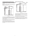
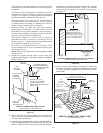
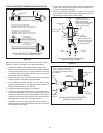
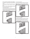
8. Cut a length(s) of pipe being installed 3.5 inches (8.9 cm)
to 9.5 inches (24.1 cm) longer than the wall thickness at the
opening. See Figure 23.
NOTE: Vent Termination – exhaust gases of this water
heater are less than 140°F. In cold climates water vapor in
the exhaust gases will condense into a cloud of vapor where
the vent exits the building. This vapor can gradually discolor
exterior building surfaces. The vent termination should be
located where this vapor cloud and potential discoloration
are not a concern. Extending the exposed vent piping up to
a maximum of 6 inches (15.2 cm) from the wall helps vapor
from being trapped along a building’s face. To avoid this
problem, the vent can also be terminated vertically through
the roof, see Vertical Termination Installation on page 24.
9. Cement the intake air and/or vent termination to the section(s)
of pipe cut to length in the above Step.
10. Slide the included metal wall plate(s) over the pipe(s) to stop
against the intake air and/or vent termination. Place some
silicone caulking (eld supplied) on the back of the wall
plate(s) to secure it to the wall.
11. Working from outside, slide the pipe and termination(s)
assembled in the above steps through the wall. Ensure the
termination(s) is pointed down towards the ground. See
Figure 23.
INTERIOR WALL EXTERIOR WALL
FROM
WATER
HEATER
COUPLING
SIDEWALL TERMINATION INSTALLATION
INTAKE AIR AND/OR VENT (EXHAUST)
METAL PLATES
INSTALL INSIDE
AND/OR OUTSIDE
FACTORY SUPPLIED
STANDARD TERMINATION
POINTED DOWN
TOWARDS THE GROUND
INCREASE EXPOSED VENT
PIPING UP TO A MAXIMUM
OF 6 INCHES (15.2 cm) FROM
WALL TO HELP PREVENT VAPOR
FROM DISCOLORING THE WALL
SURFACE IN COLDER CLIMATES
Figure 23
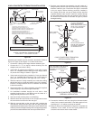
12. Place a bead of silicone caulking (eld supplied) around the
gap between the installed pipe(s) and the wall. Apply enough
to ll the gap between the pipe(s) and wall.
13. Press the wall plate ush against the outside wall.
14. Working from the inside apply enough silicone caulking on
the back of the interior wall plate(s) to hold it in place and
slide the wall plate over the installed pipe(s).
15. Install a coupling to the end of the pipe(s) inside the building.
Before the silicone caulking has time to completely set go
outside the building and ensure the termination(s) is still
pointing down towards the ground. See Figure 23.
16. Return to Power Vent Installation on page 23 or Direct Vent
Installation on page 23 to complete the installation of the intake
air and/or vent piping between the termination(s) and the
water heater.