


Installation
21
F232122
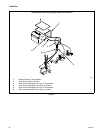
4. Reassembling the pump assembly:
a. Replace pump assembly at the rear of the
washer-extractor, resting flat on the floor.
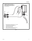
b. Secure the two pump motor electrical quick
disconnects to the water saving control
housing.
c. Replace manifold hose clamp at rear of
washer-extractor.
d. Check ball valve for closed position. Before
operating machine, ball valve must be closed.
NOTE: Pump rotation must be counterclockwise
when pump is viewed from fan end or clockwise
when viewed from plastic pump head end.
Improper rotation will cause the pump to fail
resulting in increased cycle time. Refer to rotation
arrow on pump in Figure 5. Rotation may be
corrected by exchanging two 3-phase power wires
at input power terminal block then recheck each
pump separately.
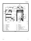
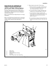
5. Replacing the water tanks:
a. Carefully replace the tanks on top of the
washer-extractor.
b. Replace the four bolts behind cap plug at each
corner of tanks.
c. Slide on short black hose to the large tank
elbow at the rear of the tank. Refer to Figure 9.
Tighten hose clamp.
d. Slide on long black hoses to the appropriate
tank elbow at the rear of each tank – right tank
to top pump, left tank to bottom pump.
Tighten hose clamps.
e. Tighten the three clamps underneath each
tank.
f. Replace the three cap plugs on each side of
the tanks.
6. Installing the tank vacuum vents:
a. Remove tank vacuum vents from packaging.
b. Apply Teflon tape to vacuum vent threads and
screw into top of each tank, tightening by
hand only.
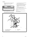
Tank Overflows
Some tank overflows have external 2" PVC
connections. These connections may be plumbed to an
open trough or floor drain.
IMPORTANT: Connections made to the overflow
must provide adequate support for weight of pipe
and fittings.
Tank damage. Connections made to the
overflow must point downward from the
tank. Routing plumbing upward will damage
tanks.
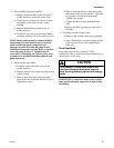
CAUTION