


Installation
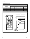
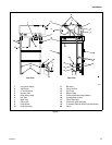
F232122
14
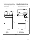
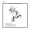
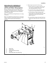
2. Installing the pump assembly (refer to Figure 5):
NOTE: The pump assembly is packaged inside
washer-extractor basket.
a. Remove the pump assembly from packaging
and place at the rear of the washer-extractor
resting flat on floor.
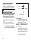
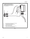
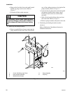
b. Route the two pump motor cable connections
to the WSS control housing (Figure 8). Slide
cable connectors in and twist to lock. Pump
cables and receptacles are marked “PA” and
“PB”. Refer to Figure 7.
c. Install large manifold hose clamp at the rear
of washer-extractor and tighten. Refer to
Figure 5.
d. Check ball valve for closed position. Before
operating machine, ball valve must be closed.
NOTE: Pump rotation must be counterclockwise
when pump is viewed from fan end or clockwise
when viewed from plastic pump head end.
Improper rotation will cause the pump to fail,
resulting in increased cycle time. Refer to rotation
arrow decal on pump and Figure 5. Rotation may
be corrected by exchanging two 3-phase power
wires on the load side of the respective contactor,
located in the remote-mounted WSS control
module.
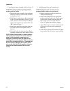
3. Installing pump hose and vacuum vents:
NOTE: Pump hoses and vacuum vents are
packaged inside washer-extractor basket.
a. Remove pump hoses and four small hose
clamps from packaging.
b. Slide on the pump hose to the appropriate
pump (top pump to right tank, bottom pump
to left tank as viewed from rear) and tank
elbow at the rear of each tank. Refer to
Figure 5. Tighten the small hose clamps.
c. Apply Teflon tape to vacuum vent threads and
screw into top of each tank, tightening by
hand only.
d. Secure the two pump hoses and the two pump
motor cables with wire ties to frame side legs.