


Installation
13
F232122
Instructions for Installation of
Pocket Hardmount Models (UWPV)
with Water Saving System
Read the following instructions thoroughly before
proceeding. The installer must have a comprehensive
understanding of the instructions before attempting
installation of the WSS. Refer to Water Saving Tank
Frame Foundation section for frame boltdown.
IMPORTANT: Ensure that the machine is installed
on a level floor of sufficient strength and that the
recommended clearances for inspection and
maintenance are provided. Never allow the
inspection and maintenance space to be blocked.
Refer to the WSS Electrical Specifications for voltage
information.
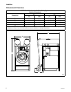
Refer to the WSS General Specifications in this
section to determine if there is adequate clearance for
the machine. If there is not and the WSS needs to be
removed, refer to the previous section “Removing Top
Section”.
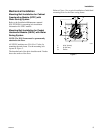
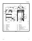
1. Connecting the WSS to washer-extractor:
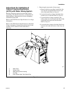
NOTE: The tank drain hose assembly is packaged
inside washer-extractor basket.
a. Remove tank drain hose assembly from
packaging. Slide drain hose over tank drain
valves and washer-extractor shell pipe. Install
large hose clamps on drain valves and small
hose clamp on shell pipe and tighten. Refer to
Figures 4 and 5.
Figure 4
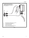
For 220V Machines:
a. For electrical hook-up, connect the control
signal cable to the “C1” (signal) quick
connect receptacle (top most plug on back of
washer-extractor control module). Connect
the power cable to the “C2” (power) quick
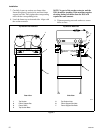
connect receptacle. Refer to Figure 7.
NOTE: Receptacles and plugs are keyed for proper
connection. For example, the control signal cable
will only fit in “C1”. Do not use excessive force
when connecting.
For 110V Machines:
a. Loosen the nut from the back of the PG9
strain relief found on the washer-extractor
control module rear. Thread 3-phase power
and green ground wires through the strain
relief and tighten the nut. Adjust extra wire
length through the strain relief, trimming off
extra length inside the control module leaving
enough to connect to input power terminal
block and ground.
b. Connect the 3-phase power wires to the input
power terminal block located inside the
washer-extractor control module.
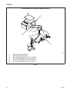
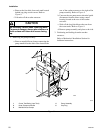
Lock out the main power panel and lock out
the power supply to the control box before
attempting any service procedures.
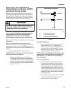
SW007
WARNING
Q038I
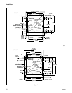
1 To Right Tank Drain Valve
2 To Left Tank Drain Valve
3 To Washer-Extractor Shell Pipe
2
1
3
Tank Drain Hose Assembly
Top View
Front View
NOTE: Right and Left are as Viewed from the Rear