


Installation
17
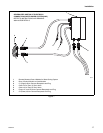
F232122
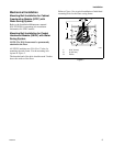
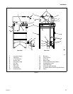
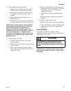
Figure 7
Q041I
1 Remote Mounted Control Module for Water Saving System
2 Rear of Control Module on Host Machine
3 C1 (Signal) Quick Connect Receptacle and Plug
4 Cable 133 to Tank “A” Drain Valve
5 Cable 132 to Tank “B” Drain Valve
6 Pumps “A” and “B” Quick Connect Receptacle and Plug
7 C2 (Power) Quick Connect Receptacle and Plug
2
3
4
5
6
7
1
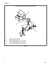
GENERALIZED SKETCH OF ELECTRICAL
CONNECTIONS WATER SAVER SYSTEM (220V)
REFER TO INSTRUCTIONS AND DRAWING
#634148 FOR DETAILS