


66307-YIM-B-0606
Unitary Products Group 39
TROUBLESHOOTING
PREDATOR
®
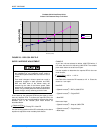
FLASH CODES
Various flash codes are utilized by the unit control board
(UCB) to aid in troubleshooting. Flash codes are
distinguished by the short on and off cycle used
(approximately 200ms on and 200ms off). To show normal
operation, the control board flashes a 1 second on, 1 second
off "heartbeat" during normal operation. This is to verify that
the UCB is functioning correctly. Do not confuse this with an
error flash code. To prevent confusion, a 1-flash, flash code
is not used.
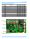
Alarm condition codes are flashed on the UCB lower left Red
LED, See Figure 23. While the alarm code is being flashed, it
will also be shown by the other LEDs: lit continuously while
the alarm is being flashed. The total of the continuously lit
LEDs equates to the number of flashes, and is shown in the
table. Pressing and releasing the LAST ERROR button on
the UCB can check the alarm history. The UCB will cycle
through the last five (5) alarms, most recent to oldest,
separating each alarm flash code by approximately 2
seconds. In all cases, a flashing Green LED will be used to
indicate non-alarm condition.
In some cases, it may be necessary to "zero" the ASCD for
the compressors in order to perform troubleshooting. To reset
all ASCDs for one cycle, press and release the UCB TEST/
RESET button once.
Flash codes that do and do not represent alarms are listed in
Table 38.
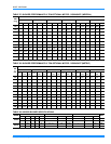
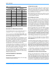
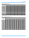
TABLE 37: COOLING SUPERHEAT 10 TON
OUTDOOR
TEMP °F
SUCTION SUPERHEAT °F
INDOOR WB TEMP °F
55 57 59 61 63 65 67 69 71 73 75
65
41.0 40.9 40.7 40.6 40.5 40.4 40.3 40.1 40.0 39.9 39.8
70
38.3 38.2 38.2 38.2 38.1 38.1 38.1 38.0 38.0 38.0 37.9
75
35.6 35.6 35.7 35.7 35.8 35.8 35.9 35.9 36.0 36.0 36.1
80
25.7 26.7 27.6 28.5 29.5 30.4 31.3 32.3 33.2 34.1 35.1
85
15.9 17.7 19.5 21.3 23.2 25.0 26.8 28.6 30.4 32.3 34.1
90
14.4 16.1 17.8 19.5 21.1 22.8 24.5 26.2 27.9 29.5 31.2
95
13.0 14.5 16.0 17.6 19.1 20.7 22.2 23.7 25.3 26.8 28.4
100
9.8 11.4 13.0 14.5 16.1 17.7 19.3 20.9 22.5 24.0 25.6
105
6.6 8.2 9.9 11.5 13.1 14.8 16.4 18.0 19.6 21.3 22.9
110
4.6 5.9 7.2 8.5 9.8 11.1 12.4 13.7 14.9 16.2 17.5
115
2.5 3.5 4.5 5.4 6.4 7.4 8.3 9.3 10.3 11.2 12.2
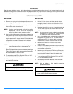
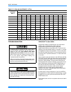
Troubleshooting of components may require open-
ing the electrical control box with the power con-
nected to the unit. Use extreme care when
working with live circuits! Check the unit name-
plate for the correct line voltage and set the voltme-
ter to the correct range before making any
connections with line terminals.
When not necessary, shut off all electric power to the
unit prior to any of the following maintenance proce-
dures so as to prevent personal injury.
Label all wires prior to disconnection when servicing
controls. Wiring errors can cause improper and dan-
gerous operation which could cause injury to person
and/or damage unit components. Verify proper oper-
ation after servicing.