


66307-YIM-B-0606
Unitary Products Group 37
• If blower rotation is in the wrong direction. Refer to
Phasing Section in general information section.
• Check blower drive belt tension.
6. Check the unit supply air (CFM).
7. Measure evaporator fan motor's amp draw.
8. Set the room thermostat fan switch to off.
9. Turn unit electrical power off.
OPERATING INSTRUCTIONS
1. Turn unit electrical power on.
NOTE: Prior to initial operation, the crankcase heaters must
be energized at least 8 hours before the system is
put into operation.
2. Set the room thermostat setting to lower than the room
temperature.
3. First stage compressors will energize after the built-in
time delay (five minutes).
4. The second stage of the thermostat will energize second
stage compressor if needed.
POST START CHECK LIST
1. Verify proper system pressures for both circuits.
2. Measure the temperature drop across the evaporator
coil.
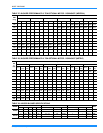
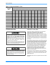
SUPERHEAT CHARGING METHOD
(Use this method if the unit is equipped with an orifice-type metering device). To determine if the system is properly charged,
connect a gauge set to the high and low service ports in the compressor compartment. A temperature probe should be attached
to the suction line near the compressor so that suction superheat can be calculated. The probe must be insulated so the higher
surrounding temperatures will not affect the reading. A measurement of the outdoor ambient and the indoor wet bulb tempera-
ture is also required. (When using a digital temperature probe it is not necessary to insulate the probe because only the probe
“tip” is used for sensing.)
Operate system until temperatures and pressures stabilize (minimum of 15 minutes). Then measure and record indoor wet bulb
(WB) temperature at the indoor coil. Insert a thermometer with a “wet sock” attached to it into the coil section. Record the out-
door dry bulb (DB) temperature using a thermometer.
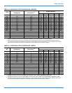
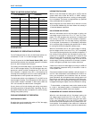
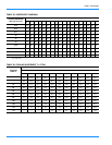
Measure and record the suction pressure at the suction service port. Using the Superheat table, note the superheat value corre-
sponding to the intersection of the indoor wet bulb and the outdoor dry bulb. With the superheat value obtained from the table
and the suction pressure value previously recorded, find the intersection of the values in Suction Tube Temperature Table. This
is the required suction tube temperature at the suction service valve.
To bring the tube temperature in line with the required value, add refrigerant to the service port to cause the tube temperature to
fall and reclaim refrigerant to cause the temperature to rise.