


66307-YIM-B-0606
30 Unitary Products Group
AIR BALANCE
Start the supply air blower motor. Adjust the resistances in both the supply and the return air duct systems to balance the air
distribution throughout the conditioned space. The job specifications may require that this balancing be done by someone other
than the equipment installer.
CHECKING AIR QUANTITY
METHOD ONE
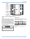
1. Remove the dot plugs from the duct panel (for location of
the dot plugs see Figure 10).
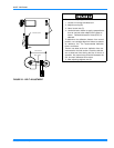
2. Insert eight-inches of 1/4 inch metal tubing into the air-
flow on both sides of the indoor coil.
NOTE: The tubes must be inserted and held in a position
perpendicular to the air flow so that velocity pres-
sure will not affect the static pressure readings.
3. Use an Inclined Manometer or Magnehelic to determine
the pressure drop across a dry evaporator coil. Since the
moisture on an evaporator coil can vary greatly, measur-
ing the pressure drop across a wet coil under field condi-
tions could be inaccurate. To assure a dry coil, the
compressors should be de-activated while the test is
being run.
NOTE: De-energize the compressors before taking any test
measurements to assure a dry evaporator coil.
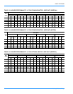
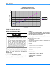
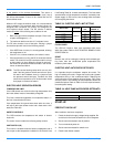
4. The CFM through the unit can be determined from the
pressure drop indicated by the manometer by referring to
Figure 23. In order to obtain an accurate measurement,
be certain that the air filters are clean.
5. To adjust Measured CFM to Required CFM, see ’SUP-
PLY AIR DRIVE ADJUSTMENT’.
6. After readings have been obtained, remove the tubes
and replace the dot plugs.
METHOD TWO
1. Drill two 5/16 inch holes, one in the return air duct as
close to the inlet of the unit as possible, and another in
the supply air duct as close to the outlet of the unit as
possible.
2. Using the holes drilled in step one, insert eight inches of
1/4 inch metal tubing into the airflow of both return and
supply air ducts of the unit.
NOTE: The tubes must be inserted and held in position per-
pendicular to the airflow so that velocity pressure
will not affect the static pressure readings.
3. Use an Inclined Manometer or Magnehelic to determine
the pressure drop across the unit. This is the External
Static Pressure (ESP). In order to obtain an accurate
measurement, be certain that the air filters are clean.
4. Determine the number of turns the variable motor
sheave is open.
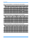
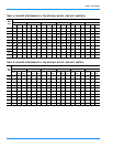
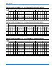
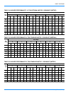
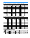
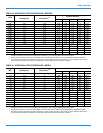
5. Select the correct blower performance table for the unit
from Tables 13 - 28. Tables are presented for horizontal
and downflow configurations.
6. Determine the unit Measured CFM from the Blower Per-
formance Table by utilizing the measured External Static
Pressure and the number of turns the variable motor
sheave is open.
7. To adjust Measured CFM to Required CFM, see ’SUP-
PLY AIR DRIVE ADJUSTMENT’.
8. After readings have been obtained, remove the tubes
and seal holes.
NOTE: With the addition of field installed accessories
repeat this procedure.
Failure to properly adjust the total system air quan-
tity can result in extensive blower damage.
Failure to properly adjust the total system air quan-
tity can result in extensive blower damage.