


66307-YIM-B-0606
Unitary Products Group 33
OPERATION
SEQUENCE OF OPERATIONS OVERVIEW
For the Predator
®
series of units, the thermostat makes a cir-
cuit between "R" and "Y1" for the first stage of cooling.
The call is passed to the Unit Control Board (UCB), which
then determines whether the requested operation is available
and, if so, which components to energize.
For heating, the thermostat makes a circuit between “R” and
“W1” for the first stage heating. The UCB energizes the com-
pressors #1 and #2 and their condenser fans. The “W1” call
also energizes a separate relay (RY1), de-energizing the
reversing valve allowing the unit to run in the heating mode. A
time/temperature control operates the defrost cycle.
The thermostat makes a circuit between “R” and “W2” for the
second stage of heating. The UCB passes the “W2” signal on
to the electric heaters if available. In both cases, when the
“W1” call is sensed, the indoor blower is energized.
If at any time a call for both heating and cooling are present,
the heating operation will be performed. If operating, the cool-
ing system is halted as with a completion of a call for cooling.
Heating always takes priority.
COOLING SEQUENCE OF OPERATION
CONTINUOUS BLOWER
By setting the room thermostat fan switch to "ON," the supply
air blower will operate continuously.
INTERMITTENT BLOWER
With the room thermostat fan switch set to "AUTO" and the
system switch set to either the "AUTO" or "HEAT" settings,
the blower is energized whenever a cooling or heating opera-
tion is requested. The blower is energized after any specified
delay associated with the operation.
When energized, the indoor blower has a minimum run time
of 30 seconds. Additionally, the indoor blower has a delay of
10 seconds between operations.
NO OUTDOOR AIR OPTIONS
When the thermostat calls for the first stage of cooling, the
low-voltage control circuit from “R” to “Y1” and “G” is com-
pleted. The UCB energizes the economizer (if installed and
free cooling is available) or the first available compressor
*
and the condenser fans. For first stage cooling, compressor
#1 is energized. If compressor #1 is unavailable, compressor
#2 is energized. After completing the specified fan on delay
for cooling, the UCB will energize the blower motor.
When the thermostat calls for the second stage of cooling,
the low-voltage control circuit from “R” to “Y2” is completed.
The control board energizes the first available compressor. If
free cooling is being used for the first stage of cooling, com-
pressor #1 is energized. If compressor #1 is active for first
stage cooling or the first compressor is locked-out, compres-
sor #2 is energized. In free-cooling mode, if the call for the
second stage of cooling continues for 20 minutes, compres-
sor #2 is energized, provided it has not been locked-out.
If there is an initial call for both stages of cooling, the UCB will
delay energizing compressor #2 by 30 seconds in order to
avoid a power rush.
Once the thermostat has been satisfied, it will de-energize Y1
and Y2. If the compressors have satisfied their minimum run
times, the compressors and condenser fans are de-ener-
gized. Otherwise, the unit operates each cooling system until
the minimum run times for the compressors have been com-
pleted. Upon the final compressor de-energizing, the blower
is stopped following the elapse of the fan off delay for cooling.
* To be available, a compressor must not be locked-out due
to a high or low-pressure switch or freezestat trip and the
anti-short cycle delay (ASCD) must have elapsed.
ECONOMIZER WITH SINGLE ENTHALPY SENSOR -
When the room thermostat calls for "first-stage" cooling, the
low voltage control circuit from "R" to "G" and "Y1" is com-
pleted. The UCB energizes the blower motor (if the fan switch
on the room thermostat is set in the "AUTO" position) and
drives the economizer dampers from fully closed to their min-
imum position. If the enthalpy of the outdoor air is below the
set point of the enthalpy controller (previously determined),
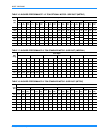
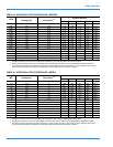
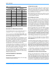
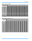
TABLE 32: MOTOR SHEAVE DATUM
1VM50x7/8
(1-1/2 & 2 HP Motor)
1VP56x1-1/8
(4 HP Motor)
Turns Open
Datum Dia.
in. (mm)
Turns Open
Datum Dia.
in. (mm)
0 4.4 (111.7) 1 5.3 (134.6)
1/2 4.3 (109.2) 1-1/2 5.2 (132)
1 4.2 (106.6) 2 5.1 (129.5)
1-1/2 4.1 (104.1) 2-1/2 5.0 (127)
2 4.0 (101.6) 3 4.9 (124.4)
2-1/2 3.9 (99) 3-1/2 4.8 (121.9)
3 3.8 (96.5) 4 4.7 (119.3)
3-1/2 3.7 (94) 4-1/2 4.6 (116.8)
4 3.6 (91.4) 5 4.5 (114.3)
4-1/2 3.5 (88.9) 5-1/2 4.4 (111.7)
5 3.4 (86.3) 6 4.3 (109.2)