


66307-YIM-B-0606
16 Unitary Products Group
comply with electrical codes should not be required. If any of
the wire supplied with the unit must be replaced, replacement
wire must be of the type shown on the wiring diagram and the
same minimum gauge as the replaced wire.
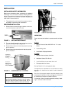
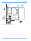
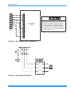
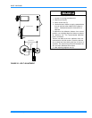
A disconnect must be utilized for these units. When installing
a disconnect, refer to Figure 4 for the recommended mount-
ing location.
NOTE: Since not all local codes allow the mounting of a dis-
connect on the unit, please confirm compliance with
local code before mounting a disconnect on the unit.
Electrical line must be sized properly to carry the load. USE
COPPER CONDUCTORS ONLY. Each unit must be wired
with a separate branch circuit fed directly from the meter
panel and properly fused.
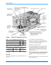
Refer to Figures 17, 18 and 19 for typical field wiring and to
the appropriate unit wiring diagram mounted inside control
doors for control circuit and power wiring information.
POWER WIRING DETAIL
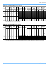
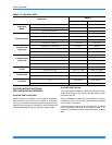
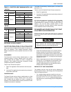
Units are factory wired for the voltage shown on the unit
nameplate. Refer to Electrical Data Tables 8 and 9 to size
power wiring, fuses, and disconnect switch.
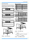
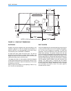
Power wiring is brought into the unit through the side of the
unit or the basepan inside the curb.
NOTE: This unit does not require a heat pump thermostat.
It is designed to work with a standard two-stage
cool, two-stage heat thermostat; however, the ther-
mostat must provide a “G” signal when there is a
call for “W1”.
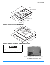
Avoid damage to internal components if drilling
holes for disconnect mounting.
When connecting electrical power and control wiring
to the unit, water-proof connectors must be used so
that water or moisture cannot be drawn into the unit
during normal operation. The above water-proofing
conditions will also apply when installing a field sup-
plied disconnect switch.
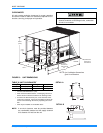
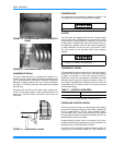
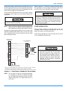
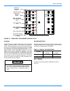
FIGURE 17 - ELECTRONIC THERMOSTAT FIELD WIRING
W 2
R C
R H
Y 1
Y 2
W 1
G
C
X 1
X 3
X 4
A 1
A 2
T
T
W 2
Y 1
Y 2
W 1
G
C
O C C
X
R
T H E R M O S T A T
1
T E R M IN A L S
U N IT T E R M I N A L S
S T R I P T B 1
1
E le c t r o n ic p r o g r a m m a b le T h e r m o s ta t 2 E T 0 7 7 0 0 1 0 0 2 4 ( in c lu d e s s u b b a s e ) .
2
T e r m in a ls A 1 a n d A 2 p r o v id e a r e la y o u tp u t t o c lo s e t h e o u td o o r
e c o n o m iz e r d a m p e r s w h e n th e t h e r m o s
t a t s w it c h e s t o th e s e t - b a c k p o s iti o n .
2 4 V o lt
T r a n s f o r m e r
2
T O R E M O T E S E N S O R
2 E T 0 4 7 0 1 3 2 4 I F U S E D
The thermostat must provide a “G” signal
when there is a call for “W1.”The unit control
board will energize the indoor blower when
the compressors are energized; however, if
the thermostat calls for “W2” during the anti-
short-cycle delay, the electric heat (when
installed) will be energized immediately
upon the call for “W2.”