


66307-YIM-B-0606
Unitary Products Group 35
and the thermostat is calling for cooling, the UCB will operate
in the low ambient mode.
Low ambient mode operates the compressors in this manner:
10 minutes on, 5 minutes off. The indoor blower is operated
throughout the cycle. The 5-minute off period is necessary to
defrost the indoor coil.
Low ambient mode always begins with compressor opera-
tion. Compressor minimum run time may extend the minutes
of compressor operation. The defrost cycle will begin immedi-
ately following the elapse of the minimum run time.
When operating in low ambient mode, the UCB will not lock-
out the compressors due to a freezestat trip. However, a
freezestat trip will de-energize the associated compressor. If
the call for cooling is still present at the end of the ASCD and
the freezestat has closed, the unit will resume operation.
SAFETY CONTROLS
The unit control board monitors the following inputs for each
cooling system:
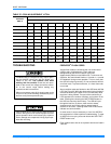
1. A suction line freezestat to protect against low evapora-
tor temperatures due to a low airflow or a low return air
temperature, (opens at 26 ± 5 °F and resets at 38 ± 5°F).
2. A high-pressure switch to protect against excessive dis-
charge pressures due to a blocked condenser coil or a
condenser motor failure, (opens at 405 ± 10 psig or
440 ± 10 psig, depending on model).
3. A low-pressure switch to protect against loss of refriger-
ant charge, (opens at 7 ± 3 psig and resets at 22 ± 5
psig).
The above pressure switches are hard-soldered to the unit.
The refrigeration systems are independently monitored and
controlled. On any fault, only the associated system will be
affected by any safety/preventive action. The other refrigerant
system will continue in operation unless it is affected by the
fault as well.
The unit control board monitors the temperature limit switch
of electric heat units and the temperature limit switch and the
gas valve of gas furnace units.
COMPRESSOR PROTECTION
In addition to the external pressure switches, the compres-
sors also have inherent (internal) protection. If there is an
abnormal temperature rise in a compressor, the protector will
open to shut down the compressor. The UCB incorporates
features to minimize compressor wear and damage. An Anti-
Short Cycle Delay (ASCD) is utilized to prevent operation of
a compressor too soon after its previous run. Additionally, a
minimum run time is imposed any time a compressor is ener-
gized.
The ASCD is initiated on unit start-up and on any compressor
reset or lock-out.
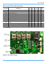
FLASH CODES
The UCB will initiate a flash code associated with errors
within the system. Refer to UNIT CONTROL BOARD FLASH
CODES Table 38.
RESET
Remove the call for cooling, by raising thermostat setting
higher than the conditioned space temperature. This resets
any pressure or freezestat flash codes.
HEATING SEQUENCE OF OPERATION
When the thermostat calls for the first stage of heating, the
low voltage control circuit is completed between “R” and
“W1”. This 24vac signal is passed through the UCB to the
RY1 Relay. Contacts RY1-1 open, assuring the reversing
valve cannot be energized, except during defrost. Contacts
RY1-2 close, completing the circuit to Y on the defrost control
(DC). After its five minute ASCD timer is satisfied, the DC
closes it’s internal compressor relay contacts, sending a
24vac signal to the MV terminal on the UCB. If its ASCD timer
is satisfied the UCB will energize compressor #1 relay. After a
two second delay, it then energizes compressor #2 relay (if
applicable). Therefore, on a call for heat from W1, both com-
pressors are always energized, unless one or the other is
locked out by the UCB. Also on the call for heat, the DC ener-
gizes the M4 contactor which brings on both condenser fans.
A second stage call from the thermostat completes the circuit
between R and W2. This 24vac signal is passed through the
UCB to the defrost control board. If the unit is equipped with
an optional electric heater it would be energized through a set
of normally closed contacts on the defrost board. Take note
that the MV terminal on the UCB is constantly monitored
while there is a demand for heat. If the UCB does not see
24vac at terminal MV after six minutes, it initiates a fault code
9, indicating a heating problem.
As mentioned earlier, the defrost control (DC) utilizes a
time/temperature defrost scheme. The following two condi-
tions must be met before the DC will enter a defrost mode:
1. The DC must first satisfy its accumulated minimum run
time. This is factory set at 60 minutes, but is field adjust-
able to 30, 60 or 90 minutes.
2. Either of the two defrost thermostats (DF1 or DF2) must
be closed. These normally open thermostats are
mounted on the respective liquid lines and are set to
close at 31 degrees (+/-3).
If neither defrost thermostat is closed at the completion of it’s
minimum accumulated run time cycle, the DC initiates
another run time cycle, which it must complete before it looks