


66307-YIM-B-0606
Unitary Products Group 15
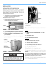
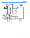
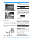
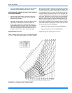
CONDENSATE DRAIN
The side condensate drain is reversible and maybe re-ori-
ented to the rear of the cabinet to facilitate condensate pip-
ing. A condensate drain connection is available through the
base pan for piping inside the roof curb. Trap the connection
per Figure 16. The trap and drain lines should be protected
from freezing.
Plumbing must conform to local codes. Use a sealing com-
pound on male pipe threads. Install condensate drain line
from the 3/4 inch NPT female connection on the unit to an
open drain.
COMPRESSORS
The compressors are mounted on elastomer insulators. The
mounting bolts have been fully tightened for shipping.
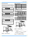
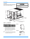
FILTERS
Two-inch filters are supplied with each unit. One-inch filters
may be used with no modification to the filter racks. Filters
must always be installed ahead of evaporator coil and must
be kept clean or replaced with same size and type. Dirty fil-
ters reduce the capacity of the unit and result in frosted coils
or safety shutdown. All units use four (4) 20”x25”x2” filters.
The unit should not be operated without filters properly
installed.
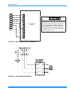
THERMOSTAT WIRING
The thermostat should be located on an inside wall approxi-
mately 56 inches above the floor where it will not be subject
to drafts, sun exposure or heat from electrical fixtures or
appliances. Follow the manufacturer's instructions enclosed
with thermostat for general installation procedure. Seven (7)
color-coded, insulated wires should be used to connect the
thermostat to the unit. Refer to Table 7 for control wire sizing
and maximum length.
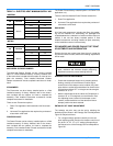
POWER AND CONTROL WIRING
Field wiring to the unit, fuses, and disconnects must conform
to provisions of National Electrical Code (NEC), ANSI/NFPA
No. 70 – Latest Edition (in U.S.A.), current Canadian Electri-
cal Code CSA C22.1, and/or local ordinances. The unit must
be electrically grounded in accordance with NEC and CEC as
specified above and/or local codes.
Voltage tolerances which must be maintained at the com-
pressor terminals during starting and running conditions are
indicated on the unit Rating Plate and Table 2.
The internal wiring harnesses furnished with this unit are an
integral part of the design certified unit. Field alteration to
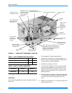
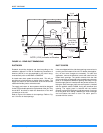
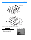
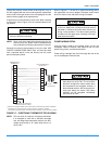
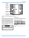
FIGURE 14 - RETURN DOWNFLOW PLENUM WITH
PANEL
FIGURE 15 - DISCHARGE PANEL IN PLACE
FIGURE 16 - CONDENSATE DRAIN
3 " M in im u m
( 7 6 .2 m m )
Do not loosen the compressor mounting bolts.
Make sure that panel latches are properly positioned
on the unit to maintain an airtight seal.
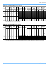
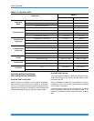
TABLE 7: CONTROL WIRE SIZES
Wire Size
Maximum Length
*
*.
From the unit to the thermostat and back to the unit.
18 AWG
150 Feet (45.72 meters)