


66307-YIM-B-0606
36 Unitary Products Group
at the position of the defrost thermostats. This action is
repeated until, at the completion of a run time cycle, one of
the defrost thermostats is found to be closed and the DC
enters defrost mode.
When the DC enters the defrost mode, it’s on-board defrost
relay is powered. This energizes both reversing valves, de-
energizes both condenser fan motors and energizes the
unit’s optional electric heater. The DC remains in defrost
mode until either
of the following two conditions is met:
1. Both of the liquid line thermostats are open. Each is set
to open at 55 degrees (+/- 3).
2. The maximum defrost run time of 10 minutes is met.
The DC also contains a set of test pins. Placing a jumper
across these pins will result in the following actions:
• If the ASCD timer is active, it is now by-passed, allowing
the compressor to run.
• If the DC is in a lockout condition, the lockout is reset.
• If the compressor is running, the DC is forced into defrost
mode. The control will remain in defrost mode for as long
as the jumper is in place. When the jumper is removed,
the control will terminate the defrost mode in the normal
manor as described above.
NOTE: The DC has two flashing codes which are only initi-
ated if the two pressure switch terminals are open.
As used in the Predator
®
, there is a jumper across
the pressure switch terminals. Therefore the field
should never experience a DC lockout mode unless
that jumper is removed or broken.
ELECTRIC HEAT OPERATION ERRORS
TEMPERATURE LIMIT
If the UCB senses zero volts from the high temperature limit,
the indoor blower motor is immediately energized.
This limit is monitored regardless of unit operation status, i.e.
the limit is monitored at all times.
If the temperature limit opens three times within one hour, it
will lock-on the indoor blower motor and a flash code is initi-
ated (See Table 38).
SAFETY CONTROLS
The UCB monitors the temperature limit switch of electric
heat units.
The control circuit includes the following safety controls:
LIMIT SWITCH (LS)
This control is located inside the heater compartment and is
set to open at the temperature indicated in the Electric Heat
Limit Setting Table 33. It resets automatically. The limit switch
operates when a high temperature condition, caused by inad-
equate supply air flow occurs, thus shutting down the heater
and energizing the blower.
FLASH CODES
The UCB will initiate a flash code associated with errors
within the system. Refer to UNIT CONTROL BOARD FLASH
CODES Table 38.
RESET
Remove the call for heating by lowering the thermostat set-
ting lower than the conditioned space temperature.This
resets any flash codes.
ELECTRIC HEAT ANTICIPATOR SETPOINTS
It is important that the anticipator setpoint be correct. Too
high of a setting will result in longer heat cycles and a greater
temperature swing in the conditioned space. Reducing the
value below the correct setpoint will give shorter “ON” cycles
and may result in the lowering of the temperature within the
conditioned space. Refer to Table 34 for the required electric
heat anticipator setting.
START-UP
PRESTART CHECK LIST
After installation has been completed:
1. Check the electrical supply voltage being supplied. Be
sure that it is the same as listed on the unit nameplate.
2. Set the room thermostat to the off position.
3. Turn unit electrical power on.
4. Set the room thermostat fan switch to on.
5. Check indoor blower rotation.
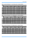
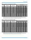
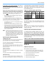
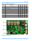
TABLE 33: ELECTRIC HEAT LIMIT SETTING
UNIT (TONS VOLTAGE
HEATER
kW
LIMIT SWITCH
OPENS °F
7.5
380/415
9150
7.5,10 18 150
7.5,10 24 150
7.5,10 34 150
10 54 140
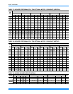
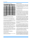
TABLE 34: HEAT PUMP ANTICIPATOR SETPOINTS
SETTING, AMPS
W1 W2
0.13 0.1