


Step 7: Configuration
15
C
W
RH
RC
Y
G
O W2
C B
G A
RH RC
W Y
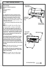
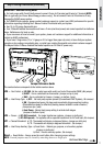
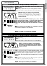
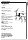
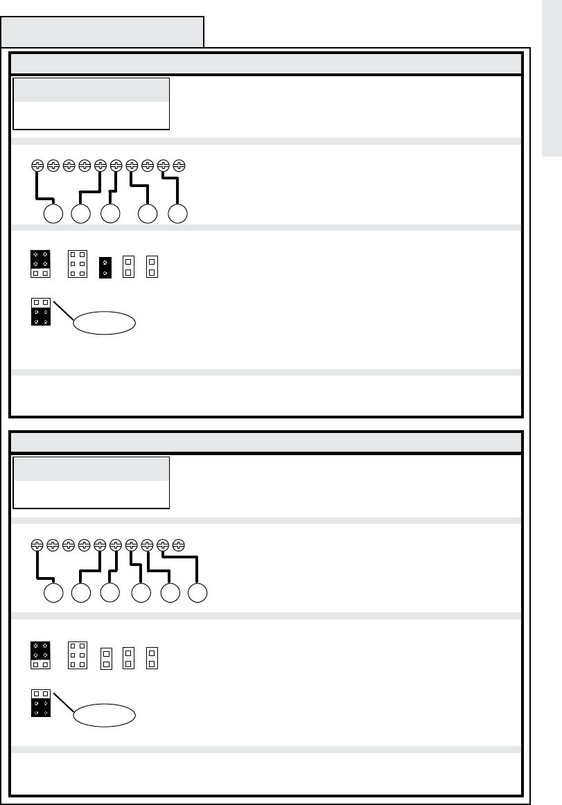
STEP B: Connect your wires to the corresponding
terminals on the thermostat base. Wrap wire around
terminal screw and tighten securely using a Phillips or
slotted screwdriver.
STEP A: Verify your labeled wires match the ones shown in the
box to the left.
NOTE: Do not allow the wires to contact another terminal,
touch each other or touch other parts of the thermostat.
C RH W
4 Wire Heat/Cool + C Wiring and Jumper Configuration
Step D: Go to Page 18 to continue your installation.
G
Your Labeled Wires
SEE NOTE
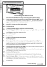
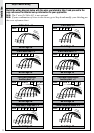
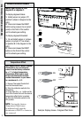
STEP C: On the Control Unit PCB, install jumpers as shown. See the
jumper reference guide on page 11 for jumper number designations.
Black indicates position of jumper, otherwise remove or do not
place jumper. Be certain jumpers are fully seated and in the correct
position.
NOTE: For Electric Heat set jumper JP5 in position A, for Gas
or Oil Heat set jumperJP5 in position B.
O W2
C B
G A
RH RC
W Y
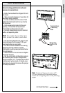
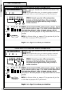
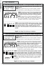
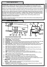
STEP B: Connect your wires to the corresponding
terminals on the thermostat base. Wrap wire around
terminal screw and tighten securely using a Phillips or
slotted screwdriver.
STEP A: Verify your labeled wires match the ones shown in the
box to the left.
NOTE: Do not allow the wires to contact another terminal,
touch each other or touch other parts of the thermostat.
A
OR
B
C
RC W
5 Wire Heat/Cool + C Wiring and Jumper Configuration
Step D: Go to Page 18 to continue your installation.
G
Your Labeled Wires
Y
RH Y
JP5 JP3 JP4 JP2JP1
Installation
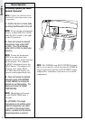
STEP C: On the Control Unit PCB, install jumpers as shown. See the
jumper reference guide on page 11 for jumper number designations.
Black indicates position of jumper, otherwise remove or do not
place jumper. Be certain jumpers are fully seated and in the correct
position.
NOTE: For Electric Heat set jumper JP5 in position A, for Gas
or Oil Heat set jumper JP5 in position B.
SEE NOTE
A
OR
B
JP5 JP3 JP4 JP2JP1
C
W
RH
G
Y