


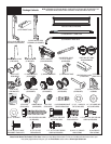
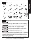

Tools Needed:
8
Please Do Not Return This Product To The Store. Contact your local Wayne-Dalton dealer. To find your local Wayne-Dalton dealer, refer to your
local yellow pages/business listings or go to the Find a Dealer section online at www.wayne-dalton.com
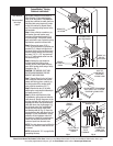
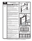
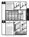
Spring tube should be free to rotate in
either direction. If the counterbalance
cable is still taut and the TorqueMaster
®
spring tube is diffi cult to rotate, that is an
indication that spring tension still exists
on the left hand spring. Repeat Steps 1
and 2 for releasing spring tension on the
left hand side.
Step 4: Using a fl at tip screwdriver, pry
the counter gear and counter cover
from the right hand end bracket (Fig. 4
on previous page). Discard the counter
gear and counter cover. On double spring
applications, repeat for left hand side.
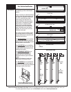
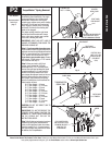
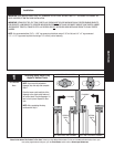
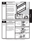
Step 5: Remove the upper 5/16” x
1-5/8” lag screw from the right hand end
bracket (Fig. 5). Attach locking pliers to
the upper portion of the end bracket and
hold the housing steady while removing
the lower 5/16” x 1-5/8” lag screw and
#10 x 1/2” phillips head screw from the
end bracket (Fig. 6).
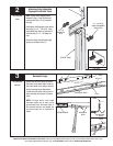
Step 6: Holding the right hand end
bracket steady with locking pliers,
carefully pry the end bracket and drive
gear off the winding shaft using a fl at tip
screwdriver (Fig. 7).
CAUTION: THE WINDING SHAFT MAY
ROTATE WHEN REMOVING THE END
BRACKET AND DRIVE GEAR.
Step 7: Repeat Step 4 for the left hand
side. Holding the left hand end bracket
steady with locking pliers, carefully pry
the end bracket off the winding shaft
using a fl at tip screwdriver (Fig. 7).
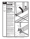
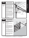
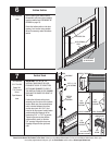
Step 8: Remove the two (2) lag bolts
attaching the center bracket assembly to
the header board (Fig. 8).
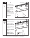
Step 9: Lift the right hand side of the
TorqueMaster
®
spring tube and slide the
cable drum off. Realign the groove in the
winding shaft with the radial notch in the
fl agangle and drape the counterbalance
cable with drum over the fl agangle. Lift
the left hand side of the TorqueMaster
®
spring tube and slide the cable drum
and winding shaft off (Fig. 9). Drape the
counterbalance cable with drum over the
fl agangle. Lift the TorqueMaster
®
spring
assembly off the fl agangles and out of
the doorway. Unhook the counterbalance
cables from the bottom brackets and
remove all parts from the work area.
NOTE: The cable drums may be diffi cult to
remove. If so, twist the cable drum to aid
in removal.
NOTE: Continue with “P4” on page 9 after
completing this step.
Fig. 5
Fig. 6
Fig. 7
Fig. 9
REMOVE TOP
LAG SCREW
REMOVE
BOTTOM LAG
SCREW
USE LOCKING PLIERS
TO HOLD END BRACKET
REMOVE #10
PHILLIPS
HEAD SCREW
PRY END BRACKET FROM WINDING
SHAFT USING A FLAT TIP SCREW
DRIVER AND LOCKING PLIERS
HOLD THE
END BRACKET
STEADY WITH
LOCKING PLIERS
REMOVE CABLE DRUM AND
WINDING SHAFT
DRAPE CABLE
ACROSS
TOP OF
FLAGANGLE
LIFT
TORQUEMASTER
®
SPRING TUBE
OFF FLAGANGLE
TorqueMaster
®
Spring
Removal continued...
Recommended
tools from
page 5
Fig. 8
CENTER
BRACKET
ASSEMBLY
(2) 5/16” X 1-5/8”
HEX HEAD LAG
SCREWS