


15
Tools Needed:
Tools Needed:
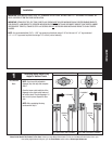
Please Do Not Return This Product To The Store. Contact your local Wayne-Dalton dealer. To find your local Wayne-Dalton dealer, refer to your
local yellow pages/business listings or go to the Find a Dealer section online at www.wayne-dalton.com
INSTALLATION
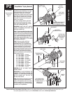
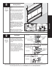
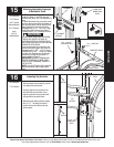
Stacking Sections
NOTE: For door section identifi cation see
page 4.
NOTE: Make sure hinges are fl ipped down,
when stacking another section on top.
Place rollers in hinge tubes of the second
section (lock section). With assistance,
lift second section and guide rollers into
the vertical tracks. Keep sections aligned
and fasten hinges to connect the sections
using 1/4”-14 x 5/8” self tapping screws.
Repeat for other section(s) except top
section.
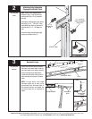
IMPORTANT: PUSH & HOLD THE HINGE
LEAF AGAINST SECTION WHILE SECURING
WITH 1/4”-14 X 5/8” SELF TAPPING
SCREWS. END HINGES HAVE (2) SCREWS
AND INTERMEDIATE HINGES HAVE (3)
SCREWS.
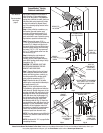
NOTE: Install lock at this time (sold
separately) see instructions in OPTIONAL
SIDELOCK INSTALLATION on page 32.
LOCK SECTION
8
(2) 1/4”-14 X 5/8”
SELF TAPPING SCREWS
END HINGES (LEFT HAND SHOWN, RIGHT
HINGE SYMMETRICALLY OPPOSITE)
INTERMEDIATE HINGES
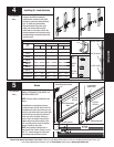
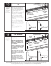
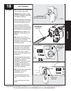
Top Brackets
(4) 1/4” - 14 x 5/8”
SELF TAPPING
SCREWS
TOP BRACKET BASE
TOP BRACKET SLIDE
(2) 1/4” - 20
FLANGED HEX
NUTS
(2) 1/4” - 20 x 5/8”
CARRIAGE BOLTS
ROLLER
TOP BRACKET SLIDE
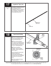
Power Drill
7/16” Socket
Driver
Power Drill
7/16” Socket
Driver
1ST SET
2ND SET
To install the L-shaped top brackets,
align the top holes in the top bracket
base with the second set of holes in the
endcap.
Fasten using (4) 1/4” - 14 x 5/8” self
tapping screws. Secure the top bracket
slide to the bracket base loosely using
(2) 1/4” - 20 x 5/8” carriage bolts and
(2) 1/4” - 20 fl anged hex nuts. The
bracket will be tightened and adjusted
in Step 16. Insert rollers into top bracket
slide. Repeat for other side.
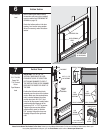
9
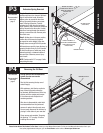
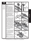
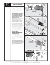
(3) 1/4”-14 X 5/8” SELF TAPPING
SCREWS
TOP SECTION
TOP SECTION
TOP SECTION