


Please Do Not Return This Product To The Store. Contact your local Wayne-Dalton dealer. To find your local Wayne-Dalton dealer,
refer to your local yellow pages business listings or go to the Find a Dealer section online at www.Wayne-Dalton.com
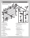
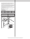
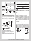
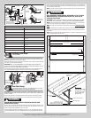
Lock section
Vertical
tracks
Center
hinge(s)
Left graduated end hinge
with short stem track roller
Left double graduated
end hinge with long
stem track roller
Right graduated end hinge
with short stem track roller
Right double graduated
end hinge with long
stem track roller
1/4”-14 x 5/8” Self tapping screw locations
Secure top
middle
hole first
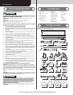
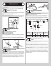
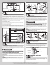
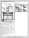
Top Fixtures
Tools: Power drill, 7/16” Socket driver, Phillips screwdriver
12
To install the top fixtures, align the top holes in the top fixture base with the second set of
holes in the end cap of the top section. Fasten to section using (4) 1/4”-14 x 5/8” self tap-
ping screws. Secure the top fixture slide to the fixture base loosely using (2) 1/4”-20 x 5/8”
carriage bolts and (2) 1/4”-20 flange hex nuts.
Fasten (2) Quadrex Pan Head screws, one in the middle hole of the top fixture base and the
other in the corresponding hole below the top fixture base.
NOTE: If you have 7’0” door height, use (2) #8 x 1-13/32” quadrex pan head screws.
NOTE: If you have 8’0” door height, use (2) #8 x 1-21/32” quadrex pan head screws.
The top fixture slide will be tightened and adjusted later, in step, Adjusting Top Fixture. Insert
short stem track roller into top fixture slide. Repeat same process for other side.
(4) 1/4”- 14 x 5/8”
Self-tapping screws
Short stem track roller
Top fixture
base
Top fixture slide
(2) 1/4”- 20
Flange hex nuts
Top section
2nd Set
End cap
(2) 1/4”- 20 x 5/8”
Carriage bolts
2nd Set
Endcap hole pattern
(2) Quadrex pan
head screws
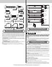
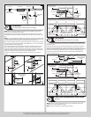
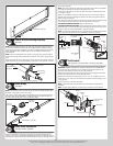
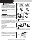
Strut (A-symmetrical)
Tools: Power drill, 7/16” Socket driver, Tape measure
13
NOTE: If an a-symmetrical strut is supplied, complete this step.
Place the a-symmetrical strut over the top rib of the top door section. Fasten each end of
the a-symmetrical strut to the end cap with (2) 1/4”-20 x 11/16” self drilling screws. Fasten
both wall and the long leg of the a-symmetrical strut, as shown using (2) 1/4”-14 x 5/8”
self tapping screws every 30-36 inches. (Approximately 18 self tapping screws per 18’
a-symmetrical strut)
IMPORTANT: WHEN SECURING THE A-SYMMETRICAL STRUT TO THE TOP SECTION, IT
IS RECOMMENDED NOT TO INSTALL ANY FASTENERS INTO THE SHORT LEG OF THE A-
SYMMETRICAL STRUT.
(2) 1/4”-14 x 5/8”
Self tapping screws
(2) 1/4”-14 x 5/8”
Self tapping screws
(2) 1/4”-20 x 11/16”
Self drilling screws
(2) 1/4”-20 x 11/16”
Self drilling screws
30” To 36”
Strut (A-symmetrical)
(attached to top rib)
End cap
Strut (A-symmetrical) side view
Short leg
Long leg
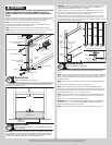
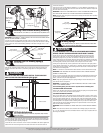
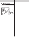
Drawbar Operator Bracket
Tools: Power drill, 7/16” Socket driver, Flat head screwdriver, 7/16”
Wrench, Tape measure, Pencil
14
IMPORTANT: WHEN CONNECTING A DRAWBAR OPERATOR TYPE GARAGE DOOR OPENER
TO THIS DOOR, A WAYNE-DALTON OPERATOR/ DRAWBAR OPERATOR BRACKET MUST
BE SECURELY ATTACHED TO THE TOP SECTION OF THE DOOR, ALONG WITH ANY STRUT
PROVIDED WITH THE DOOR. THE INSTALLATION OF THE DRAWBAR OPERATOR MUST BE AC-
CORDING TO MANUFACTURER’S INSTRUCTIONS AND FORCE SETTINGS MUST BE ADJUSTED
PROPERLY.
Position the drawbar operator bracket arm inside the top portion of the top half of drawbar
operator bracket and flush against the back of the top half of drawbar operator bracket.
Adjust the top holes in the drawbar operator bracket arm with the two upper holes in the top
half of drawbar operator bracket.
Fasten both the drawbar operator bracket arm and the top half of drawbar operator bracket
together using (2) 1/4”-20 x 9/16” track bolts and (2) 1/4”-20 flange hex nuts.
Slide the bottom half of drawbar operator bracket inside the top half of drawbar operator
bracket. Adjust the both the top and bottom halves of drawbar operator brackets out against
the top and bottom rib of the top section. Loosely fasten both the top and bottom halves of
drawbar operator brackets together using (4) 1/4”-20 x 9/16” track bolts and (4) 1/4”-20
flange hex nuts.
NOTE: Install the 1/4”-20 x 9/16” track bolts and the 1/4”-20 flange hex nuts as far apart
as possible, when positioning both the top and bottom halves of drawbar operator brackets
together.
NOTE: For retro fit applications, the drawbar operator bracket assembly must be aligned with
an existing drawbar operator.
Now, locate the center of the top section and align the center of the holes in the drawbar op-
erator bracket assembly with the top section center line. Align the drawbar operator bracket
assembly vertically.
First, secure the back of the drawbar operator bracket assembly to the top section inside
surface using (2) 1/4”-20 x 11/16” self drilling screws. Next, secure the drawbar operator
bracket assembly to the top and bottom ribs of the top section using (8) 1/4”-20 x 11/16”
self drilling screws. Now, tighten all previously installed 1/4”-20 x 9/16” track bolts and
1/4”-20 flange hex nuts.
Secure the drawbar operator bracket assembly to the top section using (1) quadrex pan head
screw.
NOTE: If you have 7’0” door height and your door width is less than or equal to 16’0”, use (1)
#8 x 1 21/32” quadrex pan head screw.
NOTE: If you have 7’0” door height and your door width is greater than 16’0”, use (1) #8 x 1
13/32” quadrex pan head screw.
NOTE: For door heights greater than 7’0”, use (1) #8 x 1 13/32” quadrex pan head screw.
(2) 1/4”-20 x9/16” Track bolts
and (2) 1/4”–20 Flange hex nuts
Drawbar operator
bracket arm
Top half of drawbar
operator bracket
Top half of drawbar
operator bracket
Bottom half of drawbar
operator bracket
Bottom rib
Top rib
(4) 1/4”-20 x9/16” Track bolts
and (4) 1/4”–20 Flange hex nuts
Top
section
inside
surface
9