


Please Do Not Return This Product To The Store. Contact your local Wayne-Dalton dealer. To find your local Wayne-Dalton dealer,
refer to your local yellow pages business listings or go to the Find a Dealer section online at www.Wayne-Dalton.com
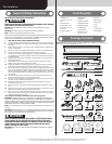
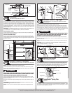
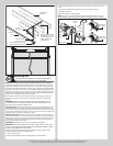
Quadrex pan
head screw
Top half of
drawbar
operator
bracket
Bottom half of drawbar
operator bracket
1/4” -20 X 11/16”
Self drilling screws
Bottom
rib
Top rib
Top section
surface
Drawbar operator
bracket arm
Top Section
Tools: Hammer, Step ladder, Tape measure
15
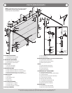
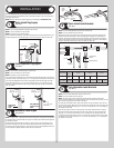
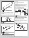
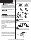
Place the top section in the opening. Temporarily secure the top section by driving a nail into
the header near the center of the door and bending it over the top section. Now, flip up the
graduated end and center hinge leaves, hold tight against section, and fasten center hinges
first and end hinges last (refer to step, Stacking Sections). Vertical track alignment is critical.
Position flag angle between 1-11/16” (43 mm) to 1-3/4” (44 mm) from the edge of the door;
tighten the bottom lag screw. Flag angles must be parallel to the door sections. Repeat same
process for other side.
IMPORTANT: THE DIMENSION BETWEEN THE FLAG ANGLES MUST BE DOOR WIDTH PLUS
3-3/8” (86MM) TO 3-1/2” (89 MM) FOR SMOOTH, SAFE DOOR OPERATION.
FOR QUICK INSTALL TRACK:
Complete the vertical track installation by securing the jamb bracket(s) and tightening the
other lag screws. Repeat for other side.
FOR FULLY ADJUSTABLE TRACK:
Complete the vertical track installation by securing the jamb bracket(s) and tightening the
other lag screws. Push the vertical track against the track rollers so that the track rollers are
touching the deepest part of the curved side of the track; tighten all the track bolts and nuts.
Repeat for other side.
Top section
Top
section
Nail
Door width
+ 3-3/8” to 3-1/2”
1-11/16”
to 1-3/4”
Flag
angle
Flag angle
Vertical track
against track rollers
Horizontal Tracks/Q.I. Flag Angles
Tools: Ratchet wrench, 9/16” Socket, 9/16” Wrench, level, Step ladder
16
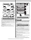
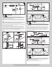
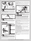
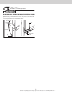
NOTE: If you have Quick Install flag angles, complete this step.
To install horizontal track, place the curved end over the top track roller of the top section.
Align key slot of the horizontal track with the Quick Install tab of the flag angle. Push curved
portion of horizontal track down to lock in place.
WARNING WARNING
DO NOT RAISE DOOR UNTIL HORIZONTAL TRACKS ARE SECURED AT REAR,
AS OUTLINED IN STEP, REAR BACK HANGS, OR DOOR COULD FALL FROM
OVERHEAD POSITION CAUSING SEVERE OR FATAL INJURY.
Level the horizontal track assembly and bolt the horizontal track angle to the first encoun-
tered slot in the flag angle using (1) 3/8”-16 x 3/4” truss head bolt and (1) 3/8”-16 hex nut.
Repeat for other side.
Remove the nail that was temporarily holding the top section in place, installed in step, Top
Section.
IMPORTANT: FAILURE TO REMOVE NAIL BEFORE ATTEMPTING TO RAISE DOOR COULD
CAUSE PERMANENT DAMAGE TO TOP SECTION.
NOTE: If an idrive
®
opener will be installed, position horizontal tracks slightly above level.
Horizontal
track
Flag angle
Quick
Install tab
Key slot
Quick
Install tab
in place
Tracks flush
3/8”-16
Hex nut
Horizontal track
angle
3/8”-16 x 3/4”
Truss head bolt
Flag angle
Horizontal Tracks/F.A. Flag Angles
Tools: Ratchet wrench, 7/16” Socket, 9/16” Socket, 9/16” Wrench,
level, Step ladder
17
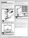
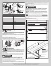
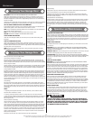
NOTE: If you have Fully Adjustable flag angles, complete this step.
To install horizontal track, place the curved end over the top track roller of the top section.
Align the bottom of the horizontal track with the top of the vertical track. If you have Quick
Install horizontal track, tighten the horizontal track to the flag angle with a stud plate and (2)
1/4”-20 flange hex nuts. If you have Universal horizontal track, tighten the horizontal track to
the flag angle with (2) 1/4”-20 x 9/16” track bolts and (2) 1/4”-20 flange hex nuts.
WARNING WARNING
DO NOT RAISE DOOR UNTIL HORIZONTAL TRACKS ARE SECURED AT REAR,
AS OUTLINED IN STEP, REAR BACK HANGS, OR DOOR COULD FALL FROM
OVERHEAD POSITION CAUSING SEVERE OR FATAL INJURY.
Level the horizontal track assembly and bolt the horizontal track angle to the first encoun-
tered slot in the flag angle using (1) 3/8”-16 x 3/4” truss head bolt and (1) 3/8”-16 hex nut.
Repeat for other side.
Remove the nail that was temporarily holding the top section in place, installed in step, Top
Section.
IMPORTANT: FAILURE TO REMOVE NAIL BEFORE ATTEMPTING TO RAISE DOOR COULD
CAUSE PERMANENT DAMAGE TO TOP SECTION.
NOTE: If an idrive
®
opener will be installed, position horizontal tracks slightly above level.
3/8”-16
Hex nut
Horizontal
track angle
3/8”-16 x 3/4”
Truss head bolt
Quick Install
horizontal
track
1/4”-20
Flange hex nuts
Stud
plate
Flag angle
upper slot
1/4”-20 x 9/16”
Track bolts
1/4”-20
Flange hex nuts
Fully Adjustable
horizontal track
Flag angle
upper slot
Adjusting Top Fixtures
Tools: 7/16” Wrench, Step ladder
18
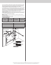
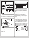
With horizontal tracks installed, you can now adjust the top fixtures. Vertically align the top
section of the door with the lower sections. Once aligned, position the top fixture slide, out
against the horizontal track. Maintaining the slide’s position, tighten the (2) 1/4”-20 flange
hex nuts to secure the top fixture slide to the top fixture base. Repeat for other side.
Top fixture slide
(2) 1/4”- 20
Flange hex nuts
Horizontal track
Top section
Top fixture base
TorqueMaster
®
Spring Tube
Tools: None
19
TorqueMaster
®
springs come lubricated and pre-assembled inside the TorqueMaster
®
spring
tube. To prepare for install, lay the spring tube assembly on the floor, inside garage, in front of
the door, and with the labeled end to the left.
10