


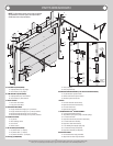

INSTALLATION
Before installing your door, be certain that you have read and followed all of the instruc-
tions covered in the pre-installation section of this manual. Failure to do so may result in an
improperly installed door.
NOTE: Reference TDS 160 for general garage door terminology at www.dasma.com.
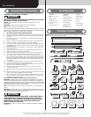
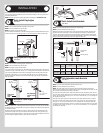
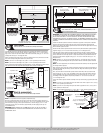
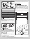
Quick Install Flag Angles
Tools: None
1
NOTE: If you have Fully Adjustable flag angles, skip this step.
NOTE: If you have riveted track, skip this step.
NOTE: Flag angles are right and left handed.
Place the lower Quick Install tab of the left hand flag angle in the Quick Install feature of the
left hand vertical track. Give the flag angle 1/4 turn to lock in place. Repeat for other side.
1/4 Turn
Flag angle
Vertical
track
Lower
Quick
Install tab
Quick
Install
feature
Fully Adjustable Flag Angles
Tools: None
2
NOTE: If you have Quick Install flag angles, skip this step.
NOTE: If you have riveted track, skip this step.
NOTE: Flag angles are right and left handed.
If you have Quick Install vertical tracks, hand tighten the left hand flag angle to the left hand
vertical track using (1) stud plate and (2) 1/4” – 20 flange hex nuts. Repeat for the other side.
If you have Fully Adjustable vertical tracks, hand tighten the left hand flag angle to the left
hand vertical track using (2) 1/4”-20 x 9/16” track bolts and (2) 1/4”-20 flange hex nuts.
Repeat for other side. Flange nuts will be secured after flag angle spacing is completed in
step, Top Section.
Quick Install
vertical
track
Stud
plate
Flag angle
1/4”-20
Flange hex nuts
1/4”- 20 x 9/16”
Track bolts
Flag angle
Fully Adjustable
vertical
track
1/4”-20
Flange hex nuts
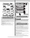
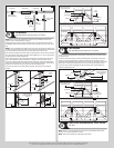
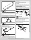
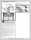
Horizontal Track Angles
Tools: Hammer
3
NOTE: For larger doors, a full length horizontal track angle may not already be spot welded to
the horizontal track. If the horizontal track angle is not welded, the horizontal track angle will
be installed, as shown.
Position the left hand horizontal track angle, as shown. Place the Quick Install tabs of the
horizontal track angle in the key slot of the left hand horizontal track. Using a hammer, tap
the horizontal track angle towards the curved end of the track until the alignment hole in the
track and angle are aligned. Repeat for other side. Set tracks aside.
Horizontal track
angle
Key slots
Horizontal
track
Alignment
hole
Quick
Install
tabs
Quick Install tabs
in place
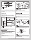
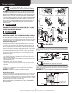
Quick Install Jamb Brackets
Tools: None
4
NOTE: If you have Fully Adjustable jamb brackets, skip this step.
NOTE: If you have riveted track, skip this step.
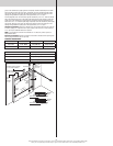
Measure the length of the vertical tracks. Using the jamb bracket schedule, determine the
placement of the jamb brackets for your door height and track length. To install the jamb
brackets, align the Quick Install tab on the Quick Install jamb bracket with the Quick Install
feature in the vertical track and turn the bracket perpendicular to the track so the mounting
flange is toward the back (flat) leg of the track. Repeat for other side.
Q.I. jamb
bracket
Jamb bracket
in place
Mounting flange
Q.I. tab
1st hole set
Bottom hole
Middle hole
Top hole
Vertical track
2nd hole set 3rd hole set
Top of track
JAMB BRACKET SCHEDULE
DOOR HEIGHT
TRACK
LENGTH
1ST SET 2ND SET 3RD SET
7’0”
76” (1930
mm)
6 B 8 B NA
8’0” 4-SEC
88”
(2235mm)
7 M 8 B 10 T
B= BOTTOM HOLE, M= MIDDLE HOLE, T= TOP HOLE
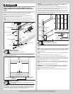
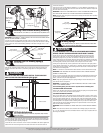
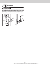
Fully Adjustable Jamb Brackets
Tools: None
5
NOTE: If you have Quick Install jamb brackets, skip this step.
NOTE: If you have riveted track, skip this step.
NOTE: The bottom jamb bracket is always the shortest bracket, while the center jamb
bracket is the next tallest. If three jamb brackets per side are included with your door, you will
have received a top jamb bracket, which is the tallest.
To attach the bottom jamb bracket, locate lower hole of the hole/ slot pattern of the 1st hole
set on the vertical track. Align the slot in the jamb bracket with the lower hole of the hole/ slot
pattern. Secure jamb bracket using (1) 1/4”-20 x 9/16” track bolt and (1) 1/4”-20 flange hex
nut. Repeat for other side.
Place the center jamb bracket over the lower hole of the hole/ slot pattern that is centered
between the bottom jamb bracket and flag angle of the 2nd hole set. Secure jamb bracket
using (1) 1/4”-20 x 9/16” track bolt and (1) 1/4”-20 flange hex nut. Repeat for other side.
If a top jamb bracket was included, secure it to vertical track using the lower hole of the hole/
slot pattern in the 3rd hole set and (1) 1/4”-20 x 9/16” track bolt and (1) 1/4”-20 flange hex
nut. Repeat for other side.
Please Do Not Return This Product To The Store. Contact your local Wayne-Dalton dealer. To find your local Wayne-Dalton dealer,
refer to your local yellow pages business listings or go to the Find a Dealer section online at www.Wayne-Dalton.com
6