


TorqueMaster
®
Plus Reset Instructions
Tools: Ratchet wrench, 5/8” Socket, 3” Socket extension, 5/8” Wrench,
(2) Vice clamps, Step ladder
IMPORTANT: THE DRAWBAR OPERATOR FORCE SETTINGS MUST BE ADJUSTED ACCORDING
TO THE MANUFACTURER’S INSTRUCTIONS. SOME LIGHTER WEIGHT DOORS ARE DESIGNED
TO OPERATE WITH A SINGLE COUNTERBALANCE SPRING. IF THAT COUNTERBALANCE SPRING
BREAKS AND THE DRAWBAR OPERATOR’S FORCE SETTINGS ARE NOT ADJUSTED ACCORDING
TO THE MANUFACTURER’S SPECIFICATIONS, THE DRAWBAR OPERATOR MAY THEN HAVE THE
CAPABILITY OF LIFTING THE DOOR TO THE OPEN POSITION, DESPITE THE BROKEN COUNTER-
BALANCE SPRING. THIS SCENARIO WILL CAUSE THE COUNTERBALANCE LIFT CABLES TO GO
SLACK AND ENGAGE THE TORQUEMASTER
®
PLUS SAFETY SYSTEM. IF A PERSON IS UNAWARE
OF THE SLACK COUNTERBALANCE LIFT CABLES AND THE ENGAGED TORQUEMASTER
®
PLUS
SAFETY SYSTEM AND ACTIVATES THE MISADJUSTED DRAWBAR OPERATOR, DAMAGE WILL
LIKELY OCCUR TO THE DOOR AND DRAWBAR OPERATOR. THE POTENTIAL ALSO EXISTS THAT
THE PERSON ACTIVATING THE DRAWBAR OPERATOR UNDER THIS SCENARIO COULD BE
SEVERELY INJURED.
WARNING WARNING
READ THESE INSTRUCTIONS CAREFULLY BEFORE ATTEMPTING TO RESET THE
TORQUEMASTER
®
PLUS SYSTEM. IF IN QUESTION ABOUT ANY OF THE PRO-
CEDURES, DO NOT PERFORM THE WORK. INSTEAD, HAVE A QUALIFIED DOOR
SYSTEMS TECHNICIAN RESET THE SYSTEM.
WARNING WARNING
TO AVOID SEVERE OR FATAL INJURY, DO NOT STAND OR WALK UNDER A
MOVING DOOR, OR PERMIT ANYONE TO STAND OR WALK UNDER AN ELECTRI-
CALLY OPERATED DOOR.
This door is equipped with a TorqueMaster
®
plus system, a safety feature which prevents the
door from rapidly descending in case of spring failure or forceful manual operation. If the system
engages with the door in the open position, personal items that are left unattended in the garage
or home are at risk to theft. To ensure the safekeeping of these items, close the garage door.
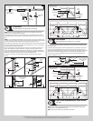
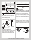
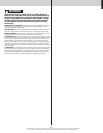
Typical signs of an engaged system.
Single spring system: Visually inspect the TorqueMaster
®
Plus right hand end bracket to con-
firm that the system has engaged (see illustration). If the system is engaged, then the door will
not close. If the drawbar operator force settings were properly set during the initial installation,
the door will not open. If the drawbar operator can physically overcome the weight of the door
and lift it to the open position, then the counterbalance lift cables will be slack. If the system is
engaged, DO NOT attempt to make the repairs. Instead, have a trained door system technician
make the necessary repairs to counterbalance lift cables, spring assemblies and other hardware.
Double spring system: Visually inspect the TorqueMaster
®
Plus end brackets to confirm
that the system has engaged (see illustration). Door will open, but will not close. Door makes a
distinct “clicking” noise upon being opened. If the system is engaged, carefully follow the reset
instructions below or refer to the reset tag (attached to right hand end bracket) to reset the
TorqueMaster
®
Plus system.
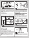
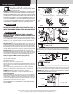
Resetting an engaged TorqueMaster
®
Plus double spring system only:
1. First, locate and visually inspect the TorqueMaster
®
plus end brackets to confirm that the
system has engaged (see illustration).
2. Disengage the drawbar operator (if installed) by pulling or placing the emergency disconnect
in the manually operated position.
3. With assistance, raise the door to the fully open position.
4. Place vice clamps onto both vertical tracks just below the bottom track roller on both sides.
5. Now is a good time to remove vehicles or personal items from garage to provide clear access
to end brackets.
6. Flip the ratchet pawl knob on both end brackets to the upper position (see illustration).
7. Raise door 2”-3” and then lower door. Repeat this process until the system resets (see
disengaged system illustrations).
IMPORTANT: BE PREPARED TO SUPPORT THE TOTAL WEIGHT OF THE DOOR.
8. Cautiously remove the vice clamps from the vertical tracks. With assistance lower door.
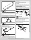
Checking springs for tension:
9. Starting on the right hand side, place a ratchet wrench, 5/8” socket and a 3” extension on the
TorqueMaster
®
Plus winding shaft (see illustration). Ensure ratchet is set so that it will tighten
counter clockwise on the right hand side, and clockwise on the left hand side. If tension is pres-
ent, remove the ratchet and check the left hand side. If spring(s) have tension, the door will need
to be balanced; refer to step, Balancing Door, to do this. If no spring tension is present, contact a
qualified trained door system technician to replace the spring(s).
IMPORTANT: TO AVOID POSSIBLE INJURY, HAVE A TRAINED DOOR SYSTEMS TECHNICIAN
MAKE ADJUSTMENTS/ REPAIRS TO COUNTERBALANCE LIFT CABLES, SPRING ASSEMBLIES
AND OTHER HARDWARE.
No space between drum pawl and
cable drum indicates engagement
Space between drum pawl and cable
drum indicates non-engagement
Ratchet
pawl
Below
view
Side
view
Drum
pawl
Drum
pawl
Cable
drum
Cable
drum
Ratchet
wrench
End bracket
Pawl
Winding
shaft
Ratchet wheel
Pawl knob in
lower position
Pawl knob in
upper position
Pawl
3”
extension
5/8” socket
TorqueMaster
®
Plus
reset instructions tag
Drum wrap
(if applicable)
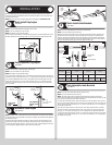
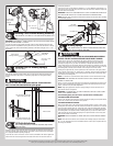
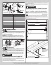
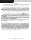
Door Arm Hookup
Tools: Needle nose pliers
Align hole in the door arm with holes in drawbar operator bracket tabs, as shown. Insert 5/16”
x 1-1/4” clevis pin, making sure hole in clevis pin is outside of second tab of drawbar operator
bracket. Insert hairpin cotter into clevis pin hole and spread hairpin cotter to secure assembly,
as shown.
Drawbar operator
bracket tabs
5/16”x 1-1/4”
Clevis pin
Cotter
pin
Spread cotter pin
Clevis pin
Door arm
Drawbar
operator bracket
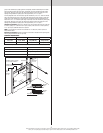
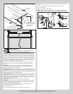
Inside Lock
Tools: Power drill, 7/16” Socket driver, Tape measure
Install the inside lock on the second section of the door. Secure the lock to the section with (4)
1/4”-20 x 11/16” self drilling screws. Square the lock assembly with the door section, and align
with the square hole in the vertical track. The inside lock should be spaced approximately 1/8”
away from the section edge.
IMPORTANT: INSIDE LOCK(S) MUST BE REMOVED OR MADE INOPERATIVE IN THE UNLOCKED
POSITION IF AN OPERATOR IS INSTALLED ON THIS DOOR.
Second section 1/8”
Inside lock
End cap
(4) 1/4”-20 x 11/16”
Self drilling screws
Square hole in
vertical track
15
Please Do Not Return This Product To The Store. Contact your local Wayne-Dalton dealer. To find your local Wayne-Dalton dealer,
refer to your local yellow pages business listings or go to the Find a Dealer section online at www.Wayne-Dalton.com
Optional Installation