


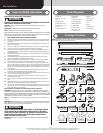
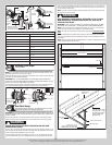

5/16” x 1 5/8” Hex head lag screws
(as required)
1/4”-20 x 11/16” Self
drilling screws (as required)
(2) 5/16”-18 x 3/4”
Carriage bolts
1/4”-20 x 9/16”
Track bolts (as required)
1/4”-14 x 5/8” Self tapping
screws (as required)
(2) 3/8”-16 x 3/4”
Truss head bolts
Cotter pin5/16” x 1-1/4” Clevis pin
Drawbar operator
bracket arm
#8 x 1-13/32” Quadrex pan head screws#8 x 1-21/32” Quadrex pan head screws
#10 x 5/8”
Phillips pan head screws
(black painted heads)
Pull handles (as required) Lift handles (as required)
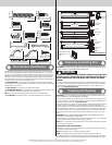
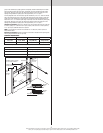
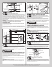
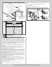
Door Section Identification
Graduated end and center hinges are always pre-attached at the top of each section (except
top section) and the graduated end hinges are stamped for identification, #1, #2, #3, and #4
(#4 only on five section doors). The stamp identifies the stacking sequence of the section. The
sequence is always determined by #1 being the bottom section to #3 or #4 being the highest
intermediate section. If the stamp on the graduated end hinge is illegible, refer to the section
side view illustration. The section side view illustration shows the graduated end hinge profile of
all sections, and can also be used to identify each section.
The BOTTOM SECTION can be identified by #1 graduated end hinges, the factory attached
bottom astragal, the factory attached bottom corner brackets, and by the bottom corner bracket
warning labels on each end stile.
The LOCK SECTION can be identified by #2 graduated end hinges.
The INTERMEDIATE SECTION can be identified by #3 graduated end hinges. The section will
have a warning label attached to either the right or left hand end stile.
NOTE: #4 graduated end hinges are used on the fourth section of five section doors.
The TOP SECTION can be identified with no pre-installed graduated end or center hinges.
Warning label
Warning label
Top section
Intermediate section
Lock section
Bottom corner bracket warning labels
Bottom section
Astragal
#3
#2
#1
#1 Graduated
end hinge
Bottom corner
bracket
Astragal
Section side view illustration
#2 Graduated
end hinge
1-1/8”
7/8”
#3 Graduated
end hinge
1-3/8”
1-9/16”
#4
Graduated
end hinge
Typical graduated end
hinge stamping
location
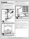
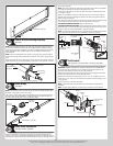
Removing an Existing Door
IMPORTANT: COUNTERBALANCE SPRING TENSION MUST ALWAYS BE RELEASED BEFORE ANY
ATTEMPT IS MADE TO START REMOVING AN EXISTING DOOR.
WARNING WARNING
A POWERFUL SPRING RELEASING ITS ENERGY SUDDENLY CAN CAUSE SEVERE
OR FATAL INJURY. TO AVOID INJURY, HAVE A TRAINED DOOR SYSTEMS TECH-
NICIAN, USING PROPER TOOLS AND INSTRUCTIONS, RELEASE THE SPRING
TENSION.
For detailed information see supplemental instructions “Removing an Existing Door/ Preparing
the Opening”. These instructions are not supplied with the door, but are available at no charge
from Wayne-Dalton, A Division Of Overhead Door Corporation, P.O. Box 67, Mt. Hope, OH.,
44660, or at www.Wayne-Dalton.com.
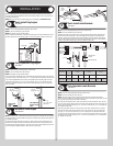
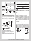
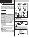
Preparing the Opening
IMPORTANT: IF YOU JUST REMOVED YOUR EXISTING DOOR OR YOU ARE INSTALLING A NEW
DOOR, COMPLETE ALL STEPS IN PREPARING THE OPENING.
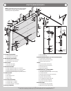
To ensure secure mounting of track brackets, side and center brackets, or steel angles to new or
retro-fit construction, it is recommended to follow the procedures outlined in DASMA technical
data sheets #156, #161 and #164 at www.dasma.com.
The inside perimeter of your garage door opening should be framed with wood jamb and header
material. The jambs and header must be securely fastened to sound framing members. It is
recommended that 2” x 6” lumber be used. The jambs must be plumb and the header level. The
jambs should extend a minimum of 12” (305 mm) above the top of the opening for TorqueMas-
ter
®
counterbalance systems. For low headroom applications, the jambs should extend to the
ceiling height. Minimum side clearance required, from the opening to the wall, is 3-1/2” (89
mm).
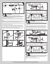
IMPORTANT: CLOSELY INSPECT JAMBS, HEADER AND MOUNTING SURFACE. ANY WOOD
FOUND NOT TO BE SOUND, MUST BE REPLACED.
For TorqueMaster
®
counterbalance systems, a suitable mounting surface (2” x 6”) must be firmly
attached to the wall, above the header at the center of the opening.
NOTE: Drill a 3/16” pilot hole in the mounting surface to avoid splitting the lumber. Do not attach
the mounting surface with nails.
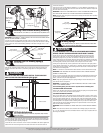
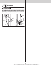
WEATHERSTRIPS (MAY NOT BE INCLUDED):
Depending on the size of your door, you may have to cut or trim the weatherstrips (if necessary)
to properly fit into the header and jambs.
NOTE: If nailing product at 40°F or below, pre-drilling is required.
NOTE: Do not permanently attach weatherstrips to the header and jambs at this time.
For Quick Install track: For the header, align the weatherstrip with the inside edge of the header
and temporarily secure it to the header with equally spaced nails. Starting at either side of the
4
Please Do Not Return This Product To The Store. Contact your local Wayne-Dalton dealer. To find your local Wayne-Dalton dealer,
refer to your local yellow pages business listings or go to the Find a Dealer section online at www.Wayne-Dalton.com