


Please Do Not Return This Product To The Store. Contact your local Wayne-Dalton dealer. To find your local Wayne-Dalton dealer,
refer to your local yellow pages business listings or go to the Find a Dealer section online at www.Wayne-Dalton.com
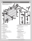
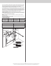
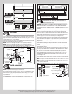
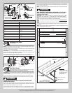
F.A. jamb
bracket
1/4”- 20 x
9/16”
Track bolt
1/4”- 20
Flange hex nut
Jamb bracket
in place
1st hole set
Lower hole of
hole/ slot pattern
Vertical track
2nd hole set 3rd hole set
Top of track
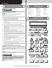
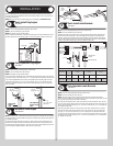
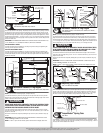
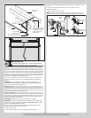
Lift Handles
Tools: Tape Measure, Pencil, Power Drill, 1/16” Drill Bit
6
NOTE: Refer to door section identification, located in the pre-installation section of this
manual or refer to Parts Breakdown on page 2.
Starting with the lock section, measure the width of the center stile which will receive the
lift handle(s). Divide that measurement in half and mark a vertical line onto the center of the
stile.
NOTE: If you are installing two lift handles on the center stile, you will need to measure from
the edge of the center stile to the center line mark. Divide that measurement in half and draw
a second and third vertical line parallel to the previously made center line mark.
Now, measure the height of the panel. Divide that measurement in half and mark a horizontal
line, intersecting the vertical line(s) previously marked. Measure up 3 7/8” from the intersect-
ing line(s) and mark another horizontal line.
Use the point(s) where the top horizontal line intersects the vertical line(s) to locate the top
hole of the lift handle(s). Using the lift handle as a template, mark this location onto the
center stile. Keeping the lift handle aligned with the vertical line, mark the lower lift handle
hole onto the center stile. Drill 1/16” pilot holes at the marked hole locations. Fasten both lift
handles to the center stile using #10 X 5/8” pan head self tapping screws.
If the door came with two sets of lift handles repeat the same process for the other lift
handles.
Lock section Lock section
(2) #10 X 5/8” Pan
head self tapping
screws
(4) #10 X 5/8” Pan
head self tapping
screws
Center line Center line
Vertical
line
Vertical
line
Lift
handle
Lift
handle
Lift
handle
Center stile
Center
stile
Center stileCenter stile
3-7/8” 3-7/8”
Horizontal
line
Horizontal
line
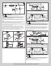
Lift handles
Bottom section
Typical placement of lift
handles referenced on
single wide doors
Lock
section
Typical placement of lift handles referenced on double wide doors
20” Minimum to
30” Maximum
20” Minimum to 30” Maximum
Pull handle
Lift handles
Bottom
section
Lock
section
Pull handle Pull handle
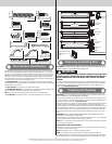
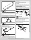
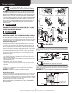
Pull Handles
Tools: Tape Measure, Pencil, Power Drill, 1/16” Drill Bit
7
Locate and mark the horizontal and vertical center on the bottom rail of the bottom section,
on single car doors.
Center the pull handle using the vertical and horizontal lines as referenced on the bottom
section rail. Using the pull handle as a template, mark the two hole locations in the pull
handle onto the horizontal line of the bottom section rail. Drill 1/16” pilot holes at the marked
hole locations. Fasten pull handle(s) using (2) #10 X 5/8” pan head self tapping screws.
If your door came with two pull handles, locate them directly below the lift handles and
repeat the installation process.
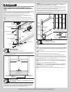
Bottom section
(2) #10 X 5/8” Pan
head self tapping
screws
Bottom rail
Center stile
Pull handle
Lift handles
Bottom section
Typical placement of pull
handle referenced on
single wide doors
Lock
section
Typical placement of pull handles referenced on double wide
20” Minimum to
30” Maximum
20” Minimum to 30” Maximum
Pull handle
Lift handles
Bottom
section
Lock
section
Pull handle Pull handle
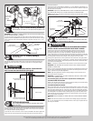
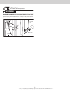
Cable Drum Assemblies and Track Rollers
Tools: None
8
NOTE: Refer to door section identification, located in the pre-installation section of this
manual or refer to Parts Breakdown on page 2.
NOTE: Cable drum assemblies are marked right and left hand.
7