


Please Do Not Return This Product To The Store. Contact your local Wayne-Dalton dealer. To find your local Wayne-Dalton dealer,
refer to your local yellow pages business listings or go to the Find a Dealer section online at www.Wayne-Dalton.com
WARNING WARNING
FAILURE TO ENSURE TIGHT FIT OF CABLE LOOP OVER MILFORD PIN COULD
RESULT IN COUNTERBALANCE LIFT CABLE COMING OFF THE PIN, AL-
LOWING THE DOOR TO FALL, POSSIBLY RESULTING IN SEVERE OR FATAL
INJURY.
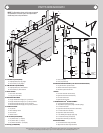
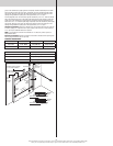
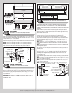
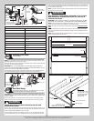
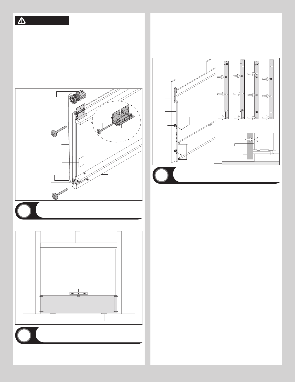
Uncoil the counterbalance lift cables from the cable drum assemblies, making sure you place
the left hand cable loop on the left hand milford pin of the bottom corner bracket and the
right hand cable loop on the right hand milford pin of the bottom corner bracket.
NOTE: Check to ensure cable loops fits tightly over the milford pins.
Insert a short stem track roller into the bottom corner brackets and another into the #1
graduated end hinges at the top of the bottom section.
NOTE: Larger doors will use long stem track rollers with double graduated end hinges.
NOTE: Verify bottom weather seal is aligned with bottom section. If there is more than 1/2”
excess weather seal on either side, trim weather seal even with bottom section.
Double graduated
end hinge (Hinge
tube)
Long stem
track roller
Counterbalance lift cable
Short stem track roller
#1 Single graduated end hinge
(Hinge tube)
Bottom corner bracket
warning label
Milford pin
Cable loop
Bottom weather seal
Bottom corner
bracket
Left hand cable
drum assembly
Bottom
section
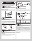
Short stem track roller
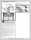
Bottom Section
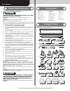
Tools: Level, Wooden shims (if necessary)
9
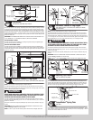
Center the bottom section in the door opening. Level the section using wooden shims (if
necessary) under the bottom section.
Weather seal
Level
Bottom section
Wooden shims
(If necessary)
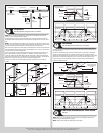
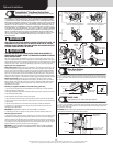
Vertical Tracks
Tools: Power Drill, 3/16” Drill bit, 7/16” Socket driver, Tape measure,
Level, Step ladder
10
IMPORTANT: IF YOUR DOOR IS TO BE INSTALLED PRIOR TO A FINISHING CONSTRUCTION
OF THE BUILDING’S FLOOR, THE VERTICAL TRACKS AND THE DOOR BOTTOM SECTION
ASSEMBLY SHOULD BE INSTALLED SUCH THAT WHEN THE FLOOR IS CONSTRUCTED, NO
DOOR OR TRACK PARTS ARE TRAPPED IN THE FLOOR CONSTRUCTION.
IMPORTANT: THE TOPS OF THE VERTICAL TRACKS MUST BE LEVEL FROM SIDE TO SIDE.
IF THE BOTTOM SECTION WAS SHIMMED TO LEVEL IT, THE VERTICAL TRACK ON THE
SHIMMED SIDE MUST BE RAISED THE HEIGHT OF THE SHIM.
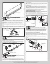
Position the left hand vertical track assembly over the track rollers of the bottom section.
Make sure the counterbalance lift cable is located between the track rollers and the door
jamb. Drill 3/16” pilot holes into the door jamb for the lag screws.
Loosely fasten jamb brackets and flag angle to the jamb using 5/16” x 1-5/8” lag screws.
Tighten lag screws, securing the bottom jamb bracket to jamb, maintain 3/8” to 5/8” spac-
ing, as shown between the bottom section and vertical track. Hang cable drum assembly over
flag angle. Repeat same process for other side.
Vertical
track
assembly
Jamb
bracket
Flag
angle
Flag angle lag screw locations
5/16” x 1-5/8”
Lag screws
Bottom
section
Track
rollers
12R FA
3/8” to 5/8”
Spacing
Bottom section
Vertical track
15R FA 15R QI12R QI
Floor
Track roller
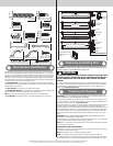
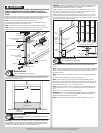
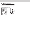
Stacking Sections
Tools: Power drill,7/16” Socket driver
11
NOTE: Refer to door section identification, located in the pre-installation section of this
manual.
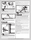
NOTE: The sections can be identified by the graduation of the factory installed graduated end
hinges. The smallest graduated end hinge on section should be stacked on top of the bottom
section, with each graduated end hinge increasing as the sections are stacked, see Parts
Breakdown on page 2.
NOTE: Make sure end and center hinges are flipped down, when stacking another section
on top.
Place track rollers into graduated end hinges of remaining sections.
NOTE: Larger doors will use long stem track rollers with double graduated end hinges.
With assistance, lift second section and guide the track rollers into the vertical tracks. Lower
section until it is seated against bottom section. Flip hinges up. Fasten center hinge(s) first;
then end hinges last using 1/4”-14 x 5/8” self tapping screws.
NOTE: To prevent center hinge leaf(s) from rotating, first secure the top middle hole of the
center hinge leaf with one 1/4” – 14 x 5/8” self-tapping screw then secure the other two
holes.
Repeat same process for other sections, except top section.
IMPORTANT: PUSH & HOLD THE HINGE LEAFS SECURELY AGAINST THE SECTIONS WHILE
SECURING WITH 1/4”-14 X 5/8” SELF TAPPING SCREWS. THERE SHOULD BE NO GAP
BETWEEN THE HINGE LEAFS AND THE SECTIONS.
NOTE: Install lock at this time (sold separately). See optional installation step, Side Lock.
8