


Please Do Not Return This Product To The Store. Contact your local Wayne-Dalton dealer. To find your local Wayne-Dalton dealer,
refer to your local yellow pages business listings or go to the Find a Dealer section online at www.Wayne-Dalton.com
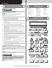
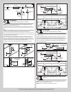
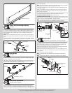
TorqueMaster
®
spring tube
Label
Center Bracket Bushing Assembly
Tools: None
20
NOTE: If you are installing the idrive
®
opener with your garage door, skip this step and go
to your idrive
®
Installation Instructions and Owner’s Manual. After completing the steps up
to and including, Drum Wrap Installation of your idrive
®
Installation Instructions and Owner’s
Manual continue with Step, Rear Back Hangs, of this door Installation Instructions and
Owner’s Manual.
NOTE: If you are not installing the idrive
®
opener on your garage door, you must install the
center bracket bushing assembly. Follow these instructions for non-idrive
®
operated garage
doors.
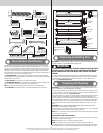
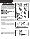
Being cam shaped, the center bushing only fits one way. Slide the center bracket bushing as-
sembly towards the center of the TorqueMaster
®
spring tube, from the right side, as shown.
Center bracket bushing assembly
TorqueMaster
®
spring tube
Center bracket
Center bushing
Cam peak
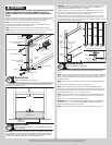
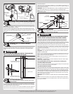
Drum Wraps
Tools: None
21
NOTE: If you don’t have drum wraps, then skip this step. Refer to Package Contents / Parts
Breakdown, to determine if you have drum wraps.
Drum wraps are marked right and left hand. Beginning with the left hand side, slide the left
hand drum wrap onto the TorqueMaster
®
spring tube. Repeat for the right hand side. The
drum wrap will be secured later, in Step, Securing Drum Wraps.
TorqueMaster
®
spring tube
Label
Left hand
drum wrap
Right hand
drum wrap
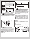
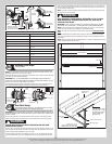
Cable Drum Assemblies
Tools: Tape measure, Step ladder
22
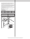
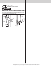
Shake the TorqueMaster
®
spring tube assembly gently to extend the winding shafts out
about 5” on each side. For single spring applications, there will be no left hand spring in the
TorqueMaster
®
spring tube assembly. Lift the TorqueMaster
®
spring tube assembly and rest it
on top of the flag angles.
NOTE: Cable drum assemblies are marked right and left hand. Cable drums and TorqueMas-
ter
®
spring tube assembly is cam shaped to fit together only one way.
Starting on the right hand side, pre-wrap the cable drum with the counterbalance lift cable
1-1/2 wraps, as shown.
Position the TorqueMaster
®
spring tube assembly so the cam peak is pointing straight up.
Slide the cable drum over the winding shaft until the cable drum seats against the Torque-
Master
®
spring tube assembly.
The winding shaft must extend past the cable drum far enough to expose the splines and the
grooves. Align the winding shaft grooves with the round notch in the flag angle.
FOR DOUBLE SPRING APPLICATIONS: Repeat for left hand side.
FOR SINGLE SPRING APPLICATIONS: Pre-wrap the left hand cable drum with the counter-
balance lift cable 1-1/2 wraps and insert the loose winding shaft into the cable drum, prior to
sliding the cable drum over the TorqueMaster
®
spring tube assembly.
NOTE: On single spring applications, take care in handling the loose winding shaft (left hand
side), so that it does not slide back into the TorqueMaster
®
spring tube assembly.
Loose winding shaft
TorqueMaster
®
spring
tube assembly
Cam peak
straight
Winding shaft
Counterbalance lift cable
1-1/2 wraps
Grooves
Cable drum
Splines
Round notch
Winding
shaft
Right cable
drum
5”
Flag
angle
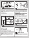
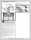
End Brackets
Tools: Power drill, 7/16” Socket driver, 1/2” Wrench, Step ladder
23
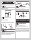
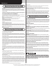
IMPORTANT: WARNING TAGS MUST BE SECURELY ATTACHED TO BOTH END BRACKETS.
End brackets are right and left hand. You can identify the right hand end bracket by the
disconnect cable guide hole, located at the top of the end bracket.
Beginning with the right hand side, slide the end bracket onto the winding shaft so that the
splines in the ratchet wheel fit onto the winding shaft grooves.
Attach the end bracket to the flag angle using (1) 5/16”-18 x 3/4” carriage bolt, (1) 5/16”
washer and (1) 5/16”-18 hex nut. Then secure the end bracket to the jamb using (1) 5/16” x
1-5/8” lag screw.
Repeat same process for left hand end bracket.
NOTE: If ratchet wheel falls out of end bracket, refer to illustration for proper insertion
orientation.
NOTE: On single spring applications, no ratchet wheel is required on the left hand side.
Grooves
Warning tag
Disconnect cable
guide hole
Splines
Winding
shaft
Right hand end bracket
Flag angle
11