


Please Do Not Return This Product To The Store. Contact your local Wayne-Dalton dealer. To find your local Wayne-Dalton dealer,
refer to your local yellow pages business listings or go to the Find a Dealer section online at www.Wayne-Dalton.com
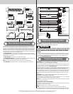
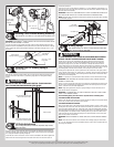
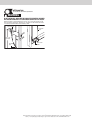
Ratchet wheel
(teeth pointing
upwards)
Black tooth
5/16” x 1-5/8”
Lag screw
5/16” -18 x 3/4”
Carriage bolt
5/16”
Washer
Flag angle
5/16” Hex nut
Right hand
end bracket
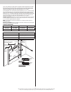
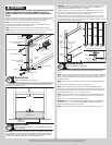
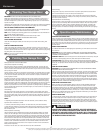
Securing Center Bracket Bushing Assembly
Tools: Power drill, 3/16” Drill bit, 7/16” Socket driver, Step ladder, Level
24
IMPORTANT: TORQUEMASTER
®
SPRING TUBE MUST BE LEVEL BEFORE SECURING CENTER
BRACKET BUSHING ASSEMBLY TO HEADER.
To locate the center bracket bushing assembly, mark the header halfway between the flag
angles and level the TorqueMaster
®
spring tube. Drill 3/16” pilot holes into header for the lag
screws. Fasten the center bracket bushing assembly to the header using (2) 5/16” x 1-5/8”
lag screws.
(2) 5/16” x 1-5/8”
Lag screws
TorqueMaster
®
spring tube
Center bracket
bushing assembly
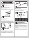
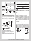
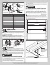
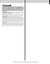
Securing Door For Winding Spring(s)
Tools: Vice Clamps
25
With the door in the fully closed position, place vice clamps onto both vertical tracks just
above the third track roller. This is to prevent the garage door from rising while winding
springs.
WARNING WARNING
FAILURE TO PLACE VICE CLAMPS ONTO VERTICAL TRACK CAN ALLOW
DOOR TO RAISE AND CAUSE SEVERE OR FATAL INJURY.
Vice clamps above third track
roller on both sides of door
Bottom section
Vice clamps attached to inner
and outer rail of vertical track
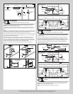
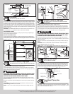
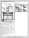
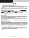
Lift Cable Adjustments
Tools: Locking pliers, Flat tip screwdriver, Step ladder, Tape measure,
Pliers/ Wire cutters
26
Starting on the right side, adjust the cable drum assembly by rotating the drum until the set
screw faces directly away from the header. The position of the cam peak on the TorqueMas-
ter
®
spring tube should be pointing straight up.
Loosen the set screw no more than 1/2 turn. Ensure counterbalance lift cable is aligned and
seated in the first and second grooves of the cable drum. Pull on the end of the cable to
remove all cable slack.
Snug the set screw and then tighten an additional 1-1/2 turns. Measure approximately 6” of
cable and cut off excess cable. Insert end of the cable into the hole of cable drum. Repeat for
left hand cable drum assembly.
IMPORTANT: ENSURE THE COUNTERBALANCE LIFT CABLE IS ALIGNED AND SEATED IN THE
FIRST AND SECOND GROOVES OF THE CABLE DRUM PRIOR TO WINDING SPRINGS.
NOTE: Illustration shows the right hand cable drum assembly, left hand cable drum assembly
is symmetrically opposite.
Cam peak
pointing straight up
Insert
cable here
6”
Cut cable here
First and
second grooves
Set screw
TorqueMaster
®
spring tube
Counterbalance
lift cable
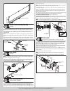
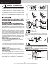
Winding Springs
Tools: Ratchet wrench, 5/8” Socket, 3” Socket extension, Pliers/ Wire
cutters, Flat tip screwdriver, Step ladder
27
WARNING WARNING
IT IS RECOMMENDED THAT LEATHER GLOVES BE WORN WHILE WINDING
SPRINGS. FAILURE TO WEAR GLOVES MAY CAUSE INJURY TO HANDS.
Double check to ensure the counterbalance lift cable is aligned in the first and second
grooves of the cable drum, see step Lift Cable Adjustments. There are two methods for
counting the spring turns as you wind. One method is to identify the black tooth on the
ratchet wheel inside of the end bracket. When the wheel makes one revolution and the tooth
returns to its starting point, one turn has been made. The other method is to make a mark on
the winding shaft (or socket) and end bracket, and count your turns in this manner.
Starting on the right hand side, turn the pawl knob on the end bracket to the upper position.
Using a ratchet wrench with a 5/8” socket and a 3” extension, wind the spring by rotating the
winding shaft counter clockwise, while watching either the black tooth on the ratchet wheel
or the mark on the winding shaft.
NOTE: A 3” extension is recommended for added clearance from the horizontal track angle.
IMPORTANT: PAWL KNOB MUST BE IN UPPER POSITION TO ADD / REMOVE REQUIRED
NUMBER OF SPRING TURNS.
After 2 to 3 turns, remove the ratchet wrench and adjust the counterbalance lift cable on the
left side. Ensure counterbalance lift cables are in the first and second grooves of the cable
drums, as shown in step Lift Cable Adjustments.
NOTE: Single spring applications require no spring winding on the left hand side, but lift
cable tension needs to be adjusted.
IMPORTANT: COUNTERBALANCE LIFT CABLE TENSION MUST BE EQUAL ON BOTH SIDES
PRIOR TO FULLY WINDING SPRINGS.
See the Winding Spring Turn Chart for the required number of winding turns:
FOR SINGLE SPRING APPLICATIONS:
Return to the right hand end bracket and continue winding the spring to the required number
of turns for your door. Place pawl knob in lower position.
FOR DOUBLE SPRING APPLICATIONS:
Either use the black tooth on the ratchet wheel for winding reference or place a mark on the
winding shaft and end bracket. Place the ratchet wrench with 5/8” socket and a 3” extension
onto the left hand winding shaft end. To wind the spring, rotate the winding shaft clockwise,
while watching the black tooth on the ratchet wheel or the mark on the winding shaft. Rotate
the winding shaft to the required number of winding turns for your door. Then return to the
right hand side and wind the right hand spring to the required number of turns. Place pawl
knob in lower position on both sides.
IMPORTANT: MARK THE NUMBER OF SPRING TURNS ONTO THE END BRACKET WARNING
TAG.
NOTE: Since total turns to balance door can deviate from winding spring turn chart values
by ± 1/2 turn, adjustments to the recommended number of turns may be required after rear
back hangs are installed.
12