


34
Please Do Not Return This Product To The Store. Contact your local Wayne-Dalton dealer.
To find your Wayne-Dalton dealer; refer to your local yellow pages / business listings or go to Find a dealer area online at www.wayne-dalton.com
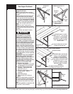
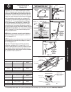
OPERATOR HOOK-UP CHART FOR LOW HEADROOM
OPERATOR MODELS
TYPE OF ARM BEING USED
PREFERRED
HOOKUP
REF. ILLUSTRA-
TIONS ABOVE
OPTIONAL
HOOKUP
REF. ILLUSTRATIONS
ABOVE
Quantum/ClassiC
CurveD /
straigHt
FIG. 3.4 straigHt FIG. 3.3
linear straigHt FIG. 3.3 n/a N/A
liftmaster
(sears)
CurveD /
straigHt
FIG. 3.4 straigHt FIG. 3.3
genie
CurveD /
straigHt
FIG. 3.4 straigHt FIG. 3.3
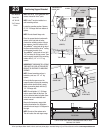
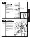
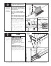
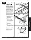
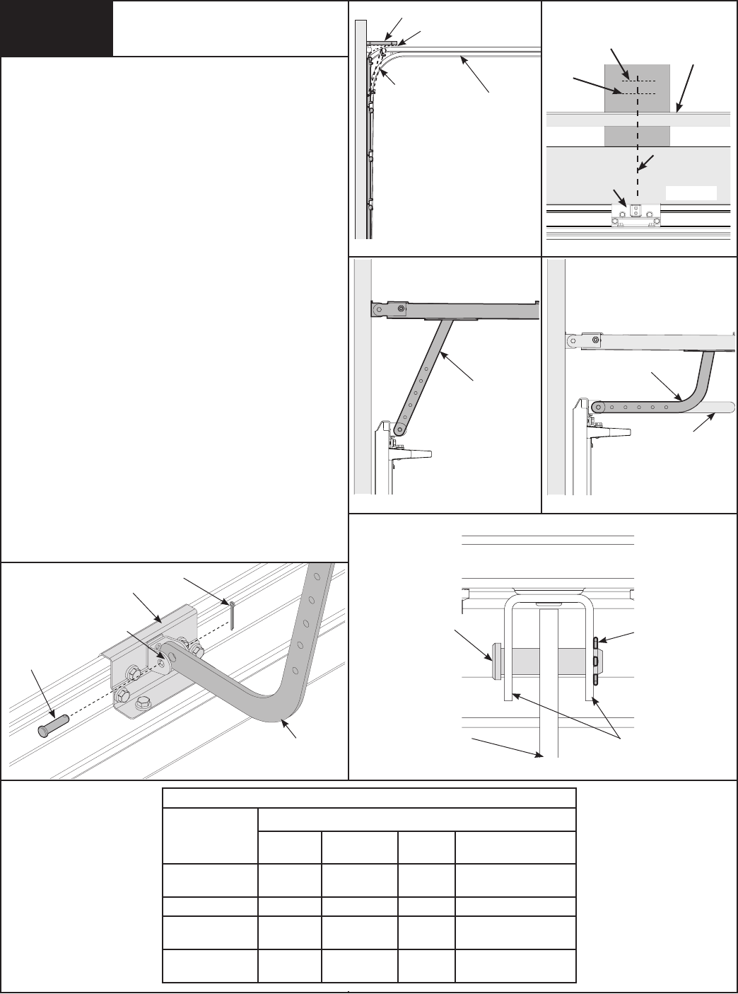
Trolley Installation for
Low Headroom
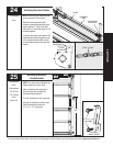
�
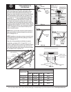
HIGH ARC
LOW
HEADROOM
TRACK
TOP
SECTION
LEVEL
FIG. 3.1
FIG. 3.2
FIG. 3.3
STRAIGHT
ARM
FIG. 3.4
CURVED
ARM
CUT STRAIGHT
ARM TO
ACCOMPLISH
TROLLEY
SETTING
Determine center line of door. Mark vertical line at this
point, on the header wall. Raise the door slightly until the
top section reaches the highest point of travel (high arc).
Using a level, mark this high arc point of travel on the header
wall, intersecting the vertical center line, as shown in FIG.
3.1 through 3.2. Hold the wall bracket’s bottom edge to the
appropriate 1/2” - 1” (room permitting) above of the high
arc line and centered on the vertical line, as shown in FIG.
3.2. Spot the wall brackets mounting holes on the header
wall and then refer to your garage door operator manual for
pre-drilling and securing the wall bracket to header. Using the
OPERATOR HOOK-UP CHARTS, refer to referenced illustrations
in FIG. 3.3 through FIG. 3.4 for correct arm hook-up from
trolley to operator bracket.
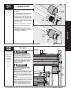
NOTE: Refer to your operator manual for specific details on
how to assembly the curved and straight arm, as shown in
FIG. 3.3 through FIG. 3.4.
NOTE: Depending on your setup, you may or may not have to
cut straight arm to accomplish trolley settings, as shown in
FIG. 3.3 through FIG. 3.4.
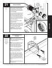
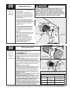
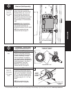
Align hole in the appropriate arm with holes in operator
bracket tabs, as shown in FIG. 3.5. Insert 5/16” x 1-1/4”
clevis pin, making sure hole in clevis pin is outside of second
tab of operator bracket. Insert hairpin cotter into clevis pin
hole and spread hairpin cotter to ensure it will secure assem-
bly, as shown in FIG. 3.5 and FIG. 3.6.
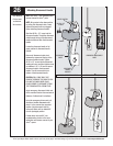
FROM
STEP 11
HIGH ARC
LINE
TYPICAL 1/2” - 1”
ABOVE HIGH ARC
VERTICAL
CENTER LINE
HEADER
TORQUEMASTER
®
COUNTERBALANCE
Hairpin Cotter
operator BraCket
Door
arm
5/16” x 1-1/4”
Clevis pin
operator
BraCket taBs
Door arm
top view
Hairpin Cotter
(outsiDe of operator
BraCket taB)
operator BraCket
taBs
FIG. 3.5
FIG. 3.6
5/16” x 1-1/4”
Clevis pin