


Tools Needed:
16
Tools Needed:
Please Do Not Return This Product To The Store. Contact your local Wayne-Dalton dealer.
To find your Wayne-Dalton dealer; refer to your local yellow pages / business listings or go to Find a dealer area online at www.wayne-dalton.com
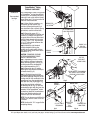
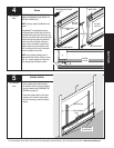
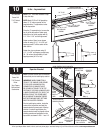
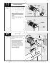
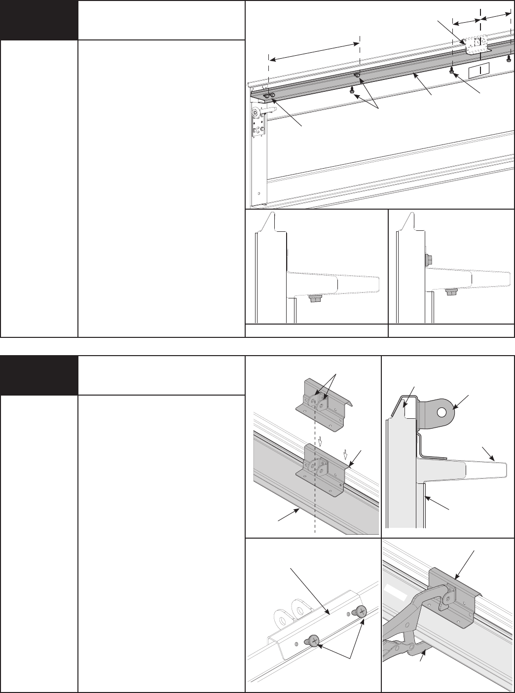
NOTE: If a 3” u-bar was installed in Step
9, skip this step.
NOTE: Model 5120 or 5140 glazed top
doors 13’-0” wide or greater will be
supplied with a 3” asymmetrical u-bar
for the top section.
Place the 3” asymmetrical u-bar over the
top rib of the top section. Fasten each
end of the u-bar to the endcap with (2)
1/4”- 20 x 11/16” self drilling screws.
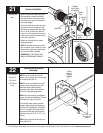
Fasten center of the u-bar as shown
to the rib using (2) 1/4”-14 x 5/8” self
tapping screws 6” off the center of the
door section.
Fasten the u-bar as shown using (2)
1/4”-14 x 5/8” self tapping screws every
30 - 36 inches. (Approximately 18 self
tapping screws per 18’ u-bar)
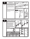
U-Bar - Asymmetrical
Power Drill
7/16” Socket
Driver
10
(2) 1/4”-20 X 11/16”
SELF DRILLING
SCREWS
(2) 1/4”- 14 X 5/8” SELF
TAPPING SCREWS
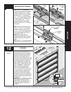
U-BAR
OPERATOR BRACKET
(INSTALLED IN THE STEP 11)
TOP DOOR SECTION
30” TO 36”
6”
6”
ATTACHING CENTER OF U-BAR
ATTACHING INTERMEDIATES OF U-BAR
(2) 1/4”-14 X 5/8”
SELF TAPPING
SCREWS
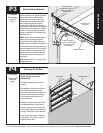
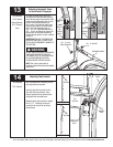
11
Power Drill
7/16” Socket
Driver
Vice Clamps
Phillips Head
Screwdriver
TOP
SECTION
WITH OR
WITHOUT
U-BAR
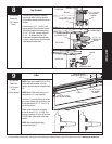
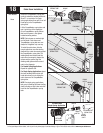
ALIGN CENTER OF BOTH TABS WITH
CENTER LINE OF TOP SECTION
OPERATOR
BRACKET
U-BAR
TOP
SECTION
OPERATOR
BRACKET
MALE PART OF
TOP SECTION
(2) #12 X 1/2”
PHILLIPS HEAD
SCREWS
VICE CLAMP
NOTE: NOT REQUIRED
FOR J-STRUTS.
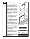
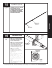
OPERATOR BRACKET
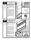
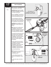
Operator Bracket
NOTE: Operator bracket must be mounted
and secured prior to installing top section.
IMPORTANT: WHEN CONNECTING A
TROLLEY TYPE GARAGE DOOR OPENER
TO THIS DOOR, A WAYNE-DALTON
OPENER/TROLLEY BRACKET MUST
BE SECURELY ATTACHED TO THE TOP
SECTION OF THE DOOR, ALONG WITH ANY
U-BARS PROVIDED WITH THE DOOR. THE
INSTALLATION OF THE OPENER MUST
BE ACCORDING TO MANUFACTURER’S
INSTRUCTIONS AND FORCE SETTINGS
MUST BE ADJUSTED PROPERLY.
Prior to installing top section, locate the
center of the top section and seat the
operator bracket on male part of the top
section. For retro fit applications, the
operator bracket must be aligned with an
existing operator and positioned on the
top section, as shown in FIG. 1.1 and 1.2.
FIG. 1.1
FIG. 1.3
FIG. 1.2
FIG. 1.4
OPPOSITE SIDE OF
OPERATOR BRACKET
U-BAR