


Tools Needed:
32
Tools Needed:
Please Do Not Return This Product To The Store. Contact your local Wayne-Dalton dealer.
To find your Wayne-Dalton dealer; refer to your local yellow pages / business listings or go to Find a dealer area online at www.wayne-dalton.com
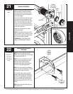
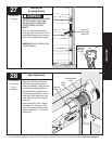
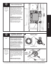
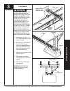
Step Plate (Sold Seperately)
Pull Rope
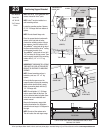
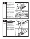
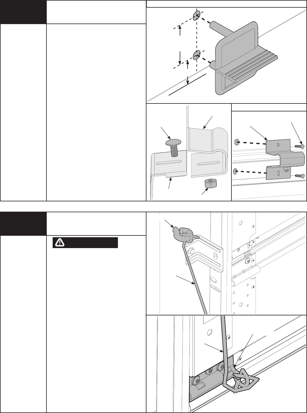
Make one mark 1” (25 mm) up from
the center of bottom edge of the bottom
section and another mark 2-3/16” (56 mm)
up from the first mark.
Drill a 7/16” (11 mm) hole through the
section at each mark and insert the outside
step plate.
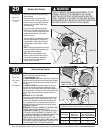
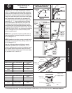
Loosely fasten step plate slide to base with
(1) 1/4” - 20 x 5/8” carriage bolt and nut.
Align inside step plate holes and fasten
from inside using the #8 screws provided.
Install one #8 x 3/4” screw in the bottom
step plate hole. The screw in the top hole
varies with door models.
Use the screw size shown below for your
model door.
a) #8 x 3/4” screw for Model 5120
b) #8 x 1” screw for Model 5140
Tighten 1/4” - 20 carriage bolt and nut.
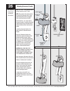
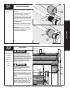
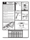
DO NOT INSTALL PULL ROPES
ON DOORS WITH ELECTRIC
OPERATORS. CHILDREN MAY
BECOME ENTANGLED IN THE
ROPE CAUSING SEVERE OR FATAL
INJURY.
Measure and mark the jamb
approximately 48” to 50” (1220 to 1270
mm) from floor on the right or left side of
door. Drill 1/8” pilot hole for No. 6 screw
eye. Tie the pull rope to the No. 6 screw
eye and to the bottom bracket as shown.
STEP PLATE INSIDE
NO. 6 SCEW EYE
PULL ROPE
BOTTOM BRACKET
PULL ROPE
7/16” Drill Bit
Power Drill
7/16" Wrench
WARNING
�
�
(2) #8 SCREWS
ASSEMBLED
STEP PLATE
1/4” - 20 X 5/8”
CARRIAGE BOLT
HEX NUT
STEP PLATE
BASE
STEP PLATE
SLIDE
Power Drill
1/8” Drill Bit
STEP PLATE OUTSIDE
1” (25mm)
2 3/16”
(56mm)