


31
Tools Needed:
Tools Needed:
Please Do Not Return This Product To The Store. Contact your local Wayne-Dalton dealer.
To find your Wayne-Dalton dealer; refer to your local yellow pages / business listings or go to Find a dealer area online at www.wayne-dalton.com
INSTALLATION
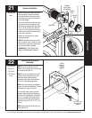
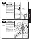
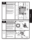
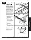
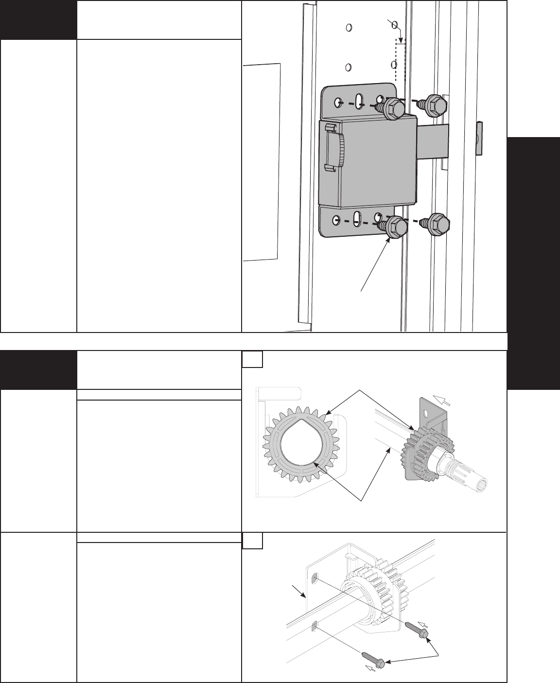
Side Lock (Sold Separately)
Install the side lock on the second
section of the door. Secure the lock to
the section with (4) 1/4”- 20 x 11/16”
self drilling screws. Square the lock
assembly with the door section and
align with the square hole in the vertical
track. The side lock should be spaced
in approximately 1/8” from the section
edge.
IMPORTANT: SIDE LOCKS MUST BE
REMOVED OR MADE INOPERATIVE IN
THE UNLOCKED POSITION IF AN
OPERATOR IS INSTALLED ON THE DOOR.
NOTE: After completing this step,
continue with Step 8 on page 15.
�
(4) 1/4”- 20 X 11/16”
SELF DRILLING SCREWS
1/8”
Power Drill
7/16” Socket
Driver
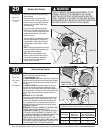
DoorMaster
TM
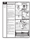
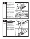
Bracket/Gear
(Supplied With Doormaster
™
)
NOTE: When installing a DoorMaster
TM
operator use the center bracket and
drive gear supplied with your operator
(located in DoorMaster
TM
package).
Slide the DoorMaster
TM
bracket/drive
gear assembly onto the TorqueMaster
®
spring tube, so that the drive gear/center
bracket assembly are in the center of
the TorqueMaster
®
spring tube.
NOTE: After completing this step,
continue with Step 18 on page 22.
None
�
CENTER
BRACKET
BUSHING
ASSEMBLY
TORQUEMASTER
®
TUBE
A
A
DOORMASTER
TM
BRACKET/
DRIVE GEAR ASSEMBLY
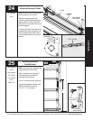
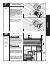
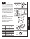
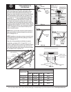
To locate the center bracket, mark the
header halfway between the flagangles
and level the TorqueMaster
®
spring tube.
Drill 1/8” pilot holes into header for the
lag screws. Fasten the metal bracket to
the header using (2) 1/4” x 1-1/2” lag
screws.
NOTE: After completing this step,
continue with Step 27 on page 28.
B
B
Tools Needed:
Power Drill
1/8” Drill Bit
7/16” Socket
Driver
(2) 1/4” X 1-1/2”
HEX HEAD LAG
SCREWS